Pallet having corrugated components and modular method of making same

a technology of corrugated components and pallets, applied in the field of pallets, can solve the problems of lack of compactness, large weight, environmental impact, etc., and achieve the effects of reducing space, enhancing the strength of the pallet and its resistance to collapse, and reducing the amount of spa

Inactive Publication Date: 2007-05-17
DIXON DOUGLASS W
View PDF36 Cites 6 Cited by
  • Summary
  • Abstract
  • Description
  • Claims
  • Application Information

AI Technical Summary

Benefits of technology

[0010] In a first embodiment, the pallet comprises two housings that are spaced-apart sleeves, each of which has a rectangular cross-sectional profile, a deck (top) panel, a bottom panel, and multiple runner structures inside the sleeves. The two sleeves are preferably spaced apart to lie at the edge extremities of the pallet, where their open ends may receive the tines of a fork lift. Preferably, each one of the two sleeves will receive a two-runner set, and the two runners in each set will be spaced apart to the edge extremities of their respective sleeves. The sleeves are sized so that a central space exists between the sleeves than runs longitudinally along the pallet, and this central space may receive at least one transverse wall for reinforcement of the pallet. Therefore, the transverse wall lies generally transverse / perpendicular to the length of the pallet, to the length of the sleeves and runners, and to the planes of both the top deck panel and the bottom panel, thus, enhancing the strength of the pallet and its resistance to collapse under a load. The top panel, bottom panel, and sleeves of this embodiment may be assembled, prior to insertion of the runners, to create a pallet frame. This frame is an intermediate version of the pallet, between the initial and final stages of assembly, that may be stored flat, and, hence, that allows storage of large quantities of frame in a much smaller amount of space than would be needed for wooden or plastic pallets.
[0011] In a second embodiment, the pallet comprises housings that are spaced-apart channels, each of which may be called a C-shape or U-shape in cross-sectional profile, runner structures that are received in each of the channels, a deck (top) panel, and a bottom panel. In the central space between the innermost channels is received at least one transverse wall that lies generally transverse / perpendicular to the length of the pallet, to the length of the channels and runner structure, and to the planes of both the top deck panel and the bottom panel, thus, enhancing the strength of the pallet and its resistance to collapse under a load. This embodiment uses even less material and less gluing, compared to the first embodiment, to create a strong and durable pallet that is remarkably light-weight.

Problems solved by technology

Wooden pallets have been in use for decades, and provide the benefits of strength and simplicity, but have the drawbacks of large weight, lack of compactness, and environmental impact due to the use of lumber.
Wooden pallets, therefore, have been blamed for many work-site injuries due to their large weight and tendency to tip over if placed on edge.
Further, wooden pallets may pose a disposal problem, frequently resulting in burning of whole pallets or pallet pieces after breakage of deck or runner members.
Plastic pallets tend to be complicated and expensive and to lack compactness.
While most corrugated pallets exhibit improved performance, compared to traditional wooden pallets, in the areas of less weight and less environmental impact, prior corrugated paper pallets have tended to be complex, weak, and / or prone to damage from forklifts.

Method used


Image

  • Pallet having corrugated components and modular method of making same
  • Pallet having corrugated components and modular method of making same
  • Pallet having corrugated components and modular method of making same

Examples


Embodiment Construction

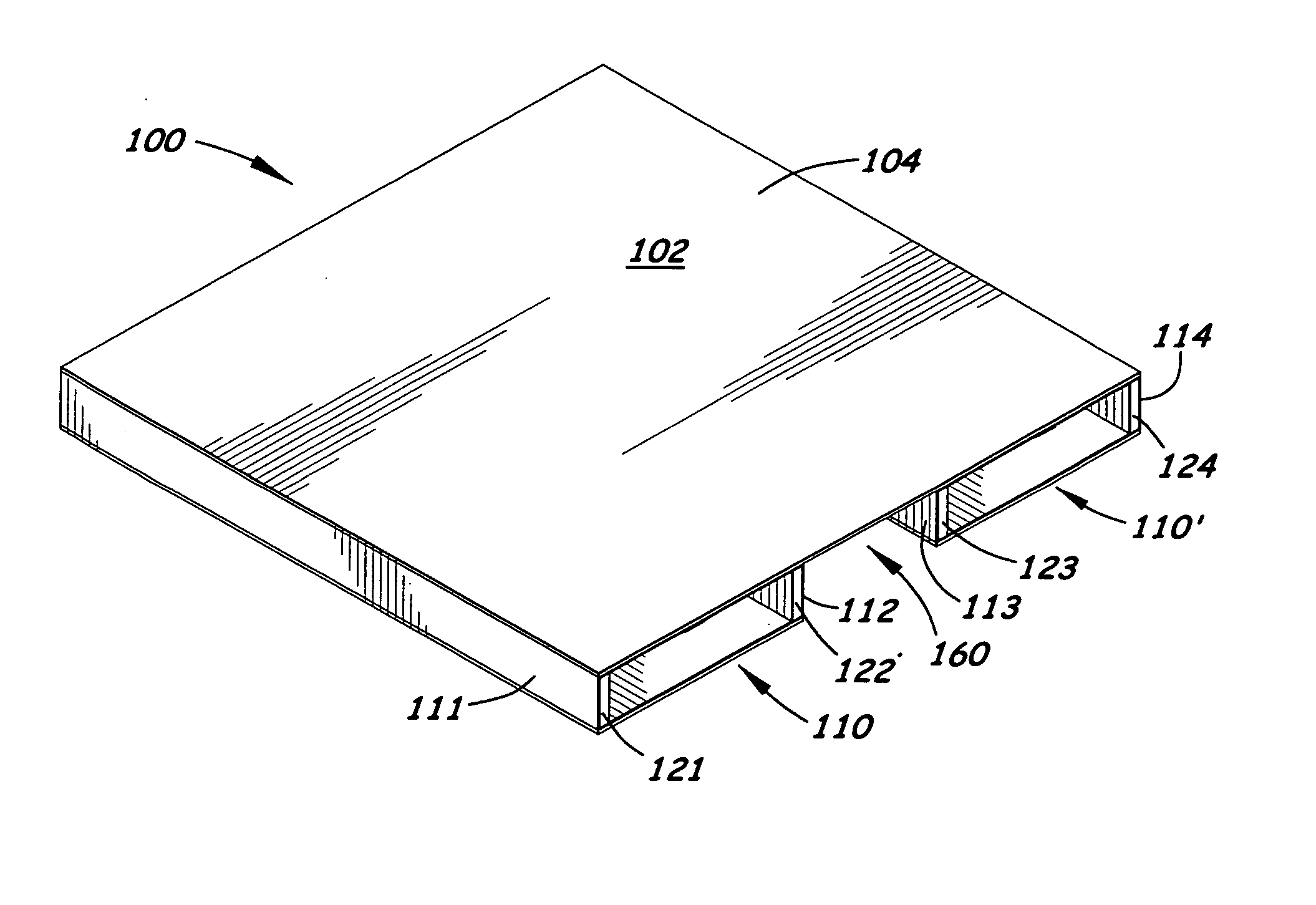
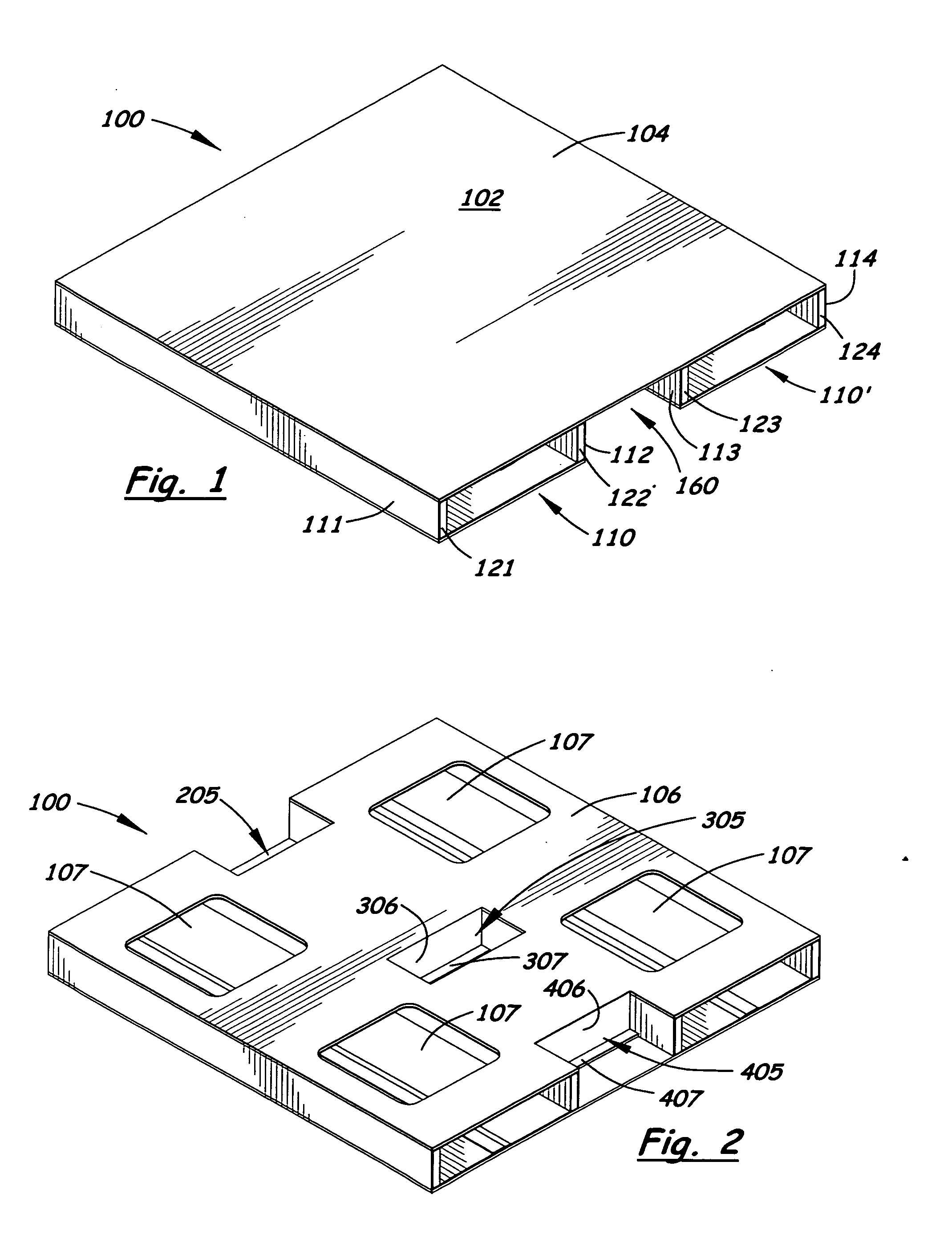
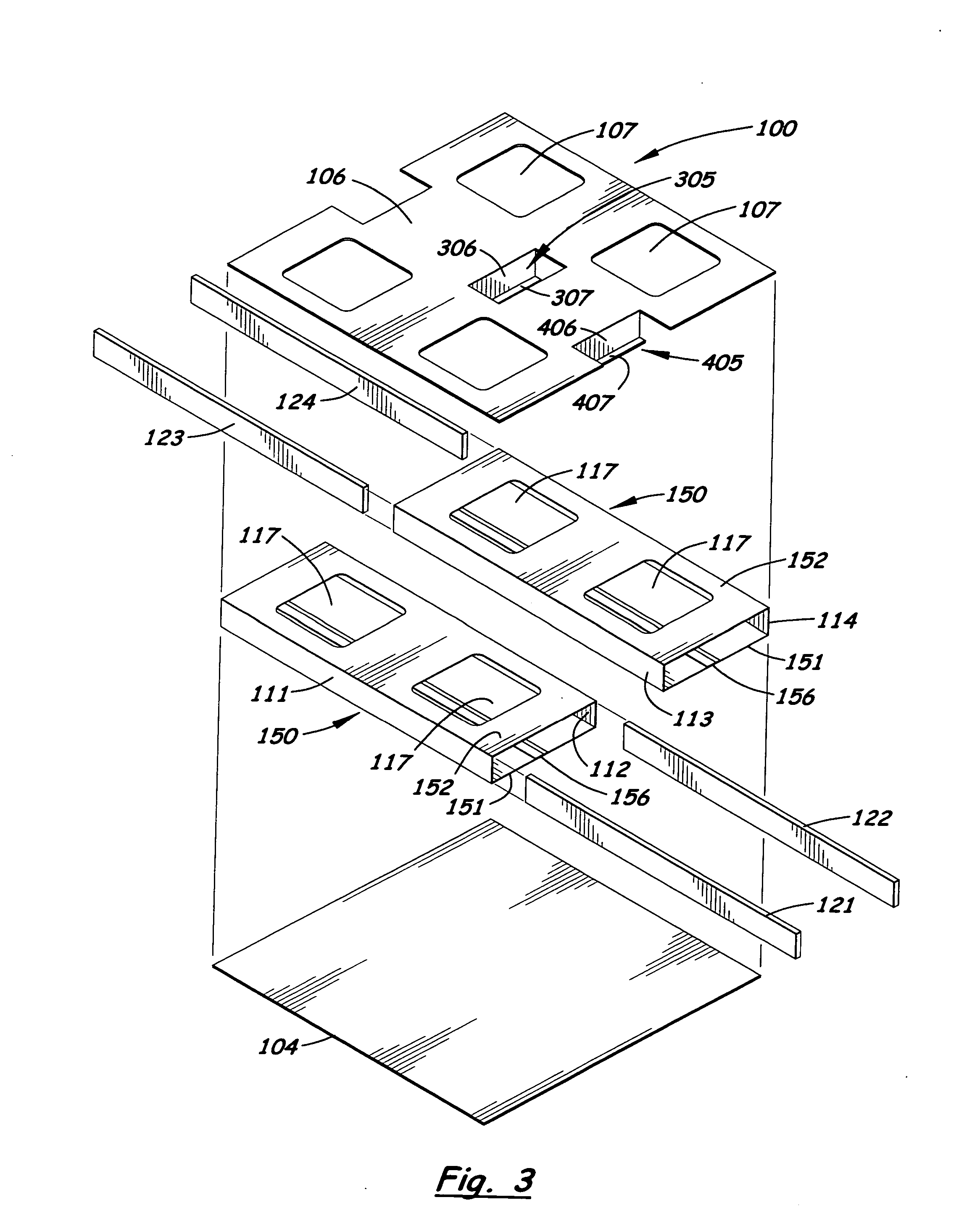
[0029] Referring to the Figures, there are shown several, but not the only, embodiments of the invented pallet. The invented pallet comprises a corrugated material and runner configuration that is particularly convenient and economical during manufacture, transport, and final assembly, and that is remarkably strong and resistant to damage from forklifts. The invented pallets are particularly effective for indoor storage and handling, however, weather-resistant coatings such as “carton coating” or covers may allow the pallets to be used outdoors at least in some climates.

[0030] The invented pallets comprise runner assemblies that run longitudinally along substantially the entire, or the entire, length of the pallet, and at least one transverse wall that extends perpendicularly to the runner assemblies, and that preferably extends between and contacts two of said runner assemblies. The preferred runner assemblies comprise housings and runner structures. The runner structures provide ...


PUM


Abstract

A pallet is made substantially or entirely of corrugated material such as corrugate cardboard. Wooden, plastic, dense foam, or composite material runners may be inserted into sleeves in the pallet, or, in other embodiments, runner channel assemblies are provided that are preferably entirely corrugate paper. Simple, modular structure allows the pallet to be made of few parts, with many of the parts being identical. Vertical securement flaps may extend between at least two of the sleeves or runner channel assemblies, thus, providing for reinforcing/securing of the relative position of the sleeve units or channel assemblies, the deck panel, and the bottom panel, to further ensure that the pallet will not collapse in use. By providing multiple longitudinal runner assemblies, with at least one transverse wall extending between two of the runner assemblies, a strong and yet lightweight pallet is provided, which may be recycled and which tends to be safe and easy to handle.

Description

[0001] This application claims priority of Provisional Application Ser. No. 60 / 733,556, filed Nov. 4, 2005; Provisional Application Ser. No. 60 / 750,845, filed Dec. 14, 2005; and Provisional Application Ser. No. 60 / 813,893, filed Jun. 14, 2006, the disclosures of which are incorporated herein by this reference.FIELD OF THE INVENTION [0002] The present invention relates generally to pallets for supporting goods during handling, transportation, and storage. The preferred embodiments are corrugated paper pallets that may be made in a modular manner, and that are lightweight, capable of supporting a large weight of goods, and resistant to damage from forklifts. RELATED ART [0003] Traditional wooden pallets, for use in warehouses, storage yards, trucks and other modes of transportation, are well-known. Examples of wooden pallet patents include Lewis, et al. (U.S. Pat. No. 2,371,106), Eberhardt (U.S. Pat. No. 2,673,700), Woodward (U.S. Pat. No. 2,982,507), and Munroe (U.S. Pat. No. 4,240,3...

Claims


Application Information

Patent Timeline
Patent Type & Authority Applications(United States)
IPC IPC(8): B65D19/00
CPCB65D19/0014B65D2519/00019B65D2519/00054B65D2519/00134B65D2519/00139B65D2519/00144B65D2519/00273B65D2519/00288B65D2519/00318B65D2519/00442B65D2519/00562
Inventor DIXON, DOUGLASS W.
Owner DIXON DOUGLASS W
Why Eureka
Try Eureka