
Piezoelectric device

a piezoelectric device and single crystal technology, applied in piezoelectric/electrostrictive transducers, device material selection, generators/motors, etc., can solve the problems of preventing the practical utilization of conventional piezoelectric devices, so as to prevent the movement of the domain wall, prevent the effect of secular deterioration of piezoelectric characteristics and large lateral

Inactive Publication Date: 2007-05-17
KAWATETABU MINING +1
View PDF5 Cites 5 Cited by
  • Summary
  • Abstract
  • Description
  • Claims
  • Application Information

AI Technical Summary

Benefits of technology

[0012] The present inventor used: a piezoelectric unimorph element and a piezoelectric bimorph element, formed by sticking a metal plate to a piezoelectric single crystal plate made such as of a Pb(Zn1 / 3Nb2 / 3) O3—PbTiO3 solid solution single crystal (for example as a specific composition, Pb[(Zn1 / 3Nb2 / 3)0.91Ti0.09] O3, hereinafter abbreviated as PZNT91 / 09) or a Pb(Mg1 / 3Nb2 / 3) O3—PbTiO3 solid solution single crystal (hereinafter abbreviated as PMNT), in which single crystals with a lateral-vibration-mode electromechanical coupling factor k31 not smaller than 70% is obtained by domain control; or an element formed by further making the single crystal plates and the metal plates repeatedly laminated with each other, and thereby, newly developed piezoelectric devices having bending-vibration-mode electromechanical coupling factors kb not smaller than 50%, 60%, respectively, and having excellent secular (aging) characteristics.
[0013] The conventional piezoelectric device using a single crystal similar to the above described single crystal has a limit in its performance, and further its piezoelectric characteristic is significantly changed (deteriorated) with the lapse of time. These two problems have prevented the practical utilization of the conventional piezoelectric device. That is, the present invention aims at providing a piezoelectric device which is made of a single crystal having a giant-lateral-effect piezoelectric characteristic improved in the piezoelectric performance, and which has less secular deterioration of the piezoelectric characteristic.
[0016] Further, in the piezoelectric device according to the present invention, six faces of the mono-domain single crystal plate are preferably used as the face for preventing the movement of the domain wall. Further, it is possible to effectively prevent the secular deterioration of the piezoelectric characteristic by using the metal plate stuck to the single crystal plate and the adhesion layer therebetween as the member for preventing the movement of the domain wall.
[0017] The piezoelectric device according to the present invention is constituted as described above, and hence, has a significantly large lateral-effect piezoelectric characteristic as compared with the conventional piezoelectric device, that is, has a giant-lateral-effect piezoelectric characteristic, which results in excellent effects that the bending-vibration-mode electromechanical coupling factor kb can be made large, and that no secular deterioration occurs in such piezoelectric characteristic. Here, “no secular deterioration” means that variation of the piezoelectric characteristic value, for example, after 10000 hours is within ±2.5% (5% in total) of the original value (immediately after polarization). Further, since the piezoelectric device according to the present invention has the excellent piezoelectric characteristics, it can be utilized in the industrial fields of various piezoelectric sensors and actuators for precision machine instruments and components, electric machines including a relay, a positioner, a motor and the like, acoustic devices including a pickup, a loudspeaker and the like, communication and information input / output media, various measurement devices, or medical appliances and instruments / auxiliary tools, and the like.

Problems solved by technology

The conventional piezoelectric device using a single crystal similar to the above described single crystal has a limit in its performance, and further its piezoelectric characteristic is significantly changed (deteriorated) with the lapse of time.
These two problems have prevented the practical utilization of the conventional piezoelectric device.

Method used


Image

  • Piezoelectric device
  • Piezoelectric device
  • Piezoelectric device

Examples


Embodiment Construction

[0028] In the following, embodiments according to the present invention are described with reference to the accompanying drawings.

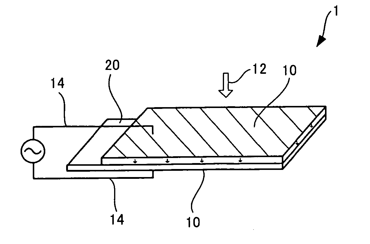
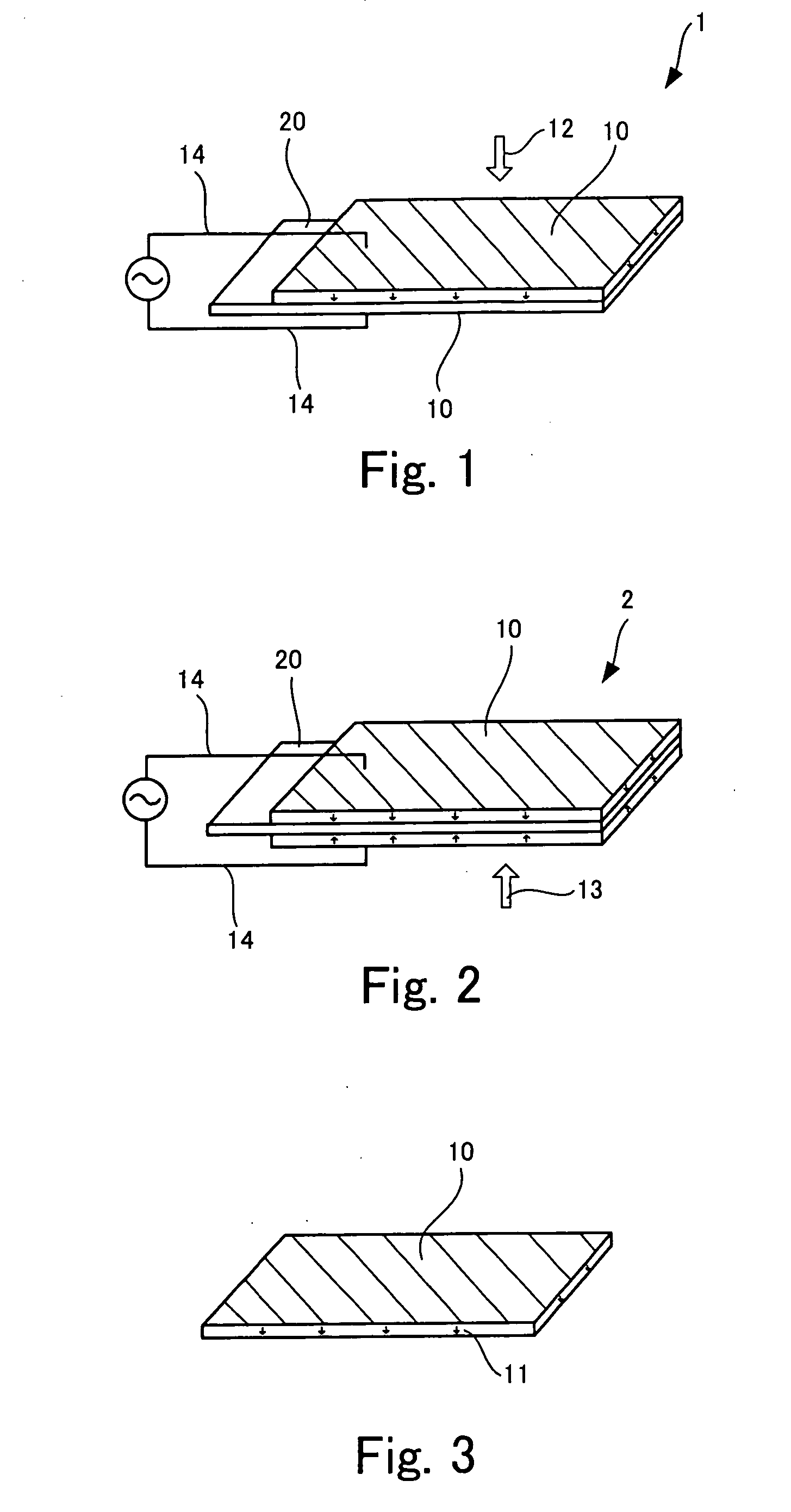
[0029]FIG. 3 is a perspective view showing a piezoelectric single crystal 10 which constitutes a piezoelectric device of an embodiment according to the present invention. The piezoelectric single crystal 10 is a plate-like piezoelectric body polarized 11 in its thickness direction by domain control, and is a mono-domain single crystal plate having a lateral-vibration-mode electromechanical coupling factor k31 not smaller than 70%, and having a piezoelectric distortion constant −d31 not smaller than 1200 pC / N, (that is, having a giant-lateral-effect piezoelectric characteristic). Such giant-lateral-effect piezoelectric characteristic is obtained only in the (100) crystal face at a polarization temperature not higher than 80° C. at which PZNT is in the form of rhombohedral, by applying a polarization field sufficient to obtain a mono-domain structure. Note...


PUM


Abstract

The present invention provides a piezoelectric device having an extremely good secular characteristic, which is a unimorph (or bimorph) element obtained by sticking to a metal plate a piezoelectric single crystal having a giant-lateral-effect piezoelectric performance of a lateral-vibration-mode electromechanical coupling factor k31 not smaller than 70%, the unimorph (or bimorph) element having a bending-vibration-mode electromechanical coupling factor kb not smaller than 50% (or 60%). A plate-form single crystal of PZNT or PMNT is brought into a mono-domain in its thickness direction and in its plate surface so as to be provided with the giant-lateral-effect piezoelectric characteristic, and the single crystal that does not cause secular deterioration is stuck to a metal plate (shim plate) while the mono-domain quality is kept as it is, as a result of which a unimorph (or bimorph) is fabricated.

Description

TECHNICAL FIELD [0001] The present invention relates to a piezoelectric device, and more particularly to a piezoelectric device having a giant-lateral-effect piezoelectric characteristic imparted thereto. BACKGROUND ART [0002] The present inventor paid attention to the fact that a piezoelectric single crystal element has an electromechanical coupling factor (k33) not smaller than 80% in the polarization direction (longitudinal vibration mode), and is thereby adapted for various usages, but nevertheless its electromechanical coupling factor (k31) in the direction (lateral vibration mode) perpendicular to the polarization direction, is 28 to 62%, which is smaller than the electromechanical coupling factor (k33) in the polarization direction (longitudinal vibration mode). Thus, the present inventor has intensively investigated the reason of the fact that the piezoelectric single crystal element has such large electromechanical coupling factor (k33) in the polarization direction (longit...

Claims


Application Information

Patent Timeline
IPC IPC(8): H01L41/187H01L41/08H01L41/09H01L41/18H01L41/22H01L41/313H03H9/17H03H9/58H04R17/00
CPCH01L41/18H03H9/176H03H9/585H01L41/094H10N30/2042H10N30/85
Inventor OGAWA
Owner KAWATETABU MINING
Learn More