Vertically-oriented centrifugal pump

Inactive Publication Date: 2007-05-17
CLEMENT ROGER B
View PDF4 Cites 5 Cited by
  • Summary
  • Abstract
  • Description
  • Claims
  • Application Information

AI Technical Summary

Benefits of technology

[0018] In order to prevent fluid that is expelled at the top of the pump from spinning in the coll

Problems solved by technology

Although it is conceivable that a single tube could be used in combination with a counterbalance, the balance w

Method used


Image

  • Vertically-oriented centrifugal pump
  • Vertically-oriented centrifugal pump
  • Vertically-oriented centrifugal pump

Examples


embodiment 100

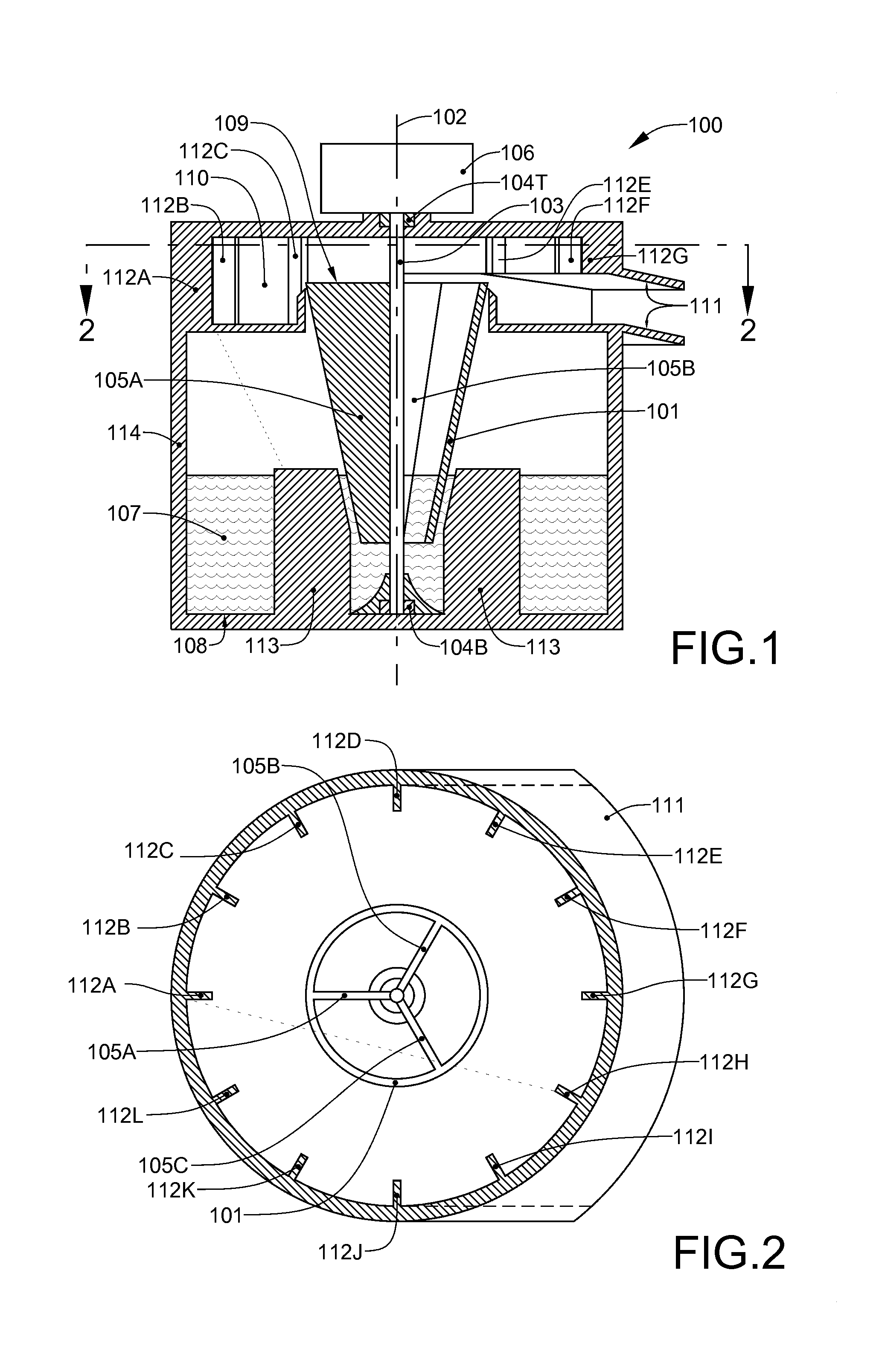
[0032] Referring now to FIGS. 1 and 2, a first primary embodiment 100 of the new centrifugal pump includes a truncated right conical member (also known as a funnel) 101 rotating about its central vertical axis 102, through which is installed a drive shaft 103. At least one and, preferably, multiple, generally vertical partitions 105A, 105B and 105C are affixed to the inner wall of the funnel. An electric motor 106 or engine applies rotational torque to the drive shaft 103. As the funnel 101 rotates, fluid 107 residing in the sump 108 enters the bottom of the funnel and begins to rotate. As it rotates, it climbs the inner wall of the funnel 101 and is expelled at the top 109 of the funnel 101 into a catch chamber 110, from whence it exits through a discharge chute 111. A circular array of baffle plates 112A-112L may be positioned around the catch chamber 110 to prevent expelled fluid from spinning therein. In addition, a plurality of anti-vortex baffles 113 are positioned within the ...

embodiment 800

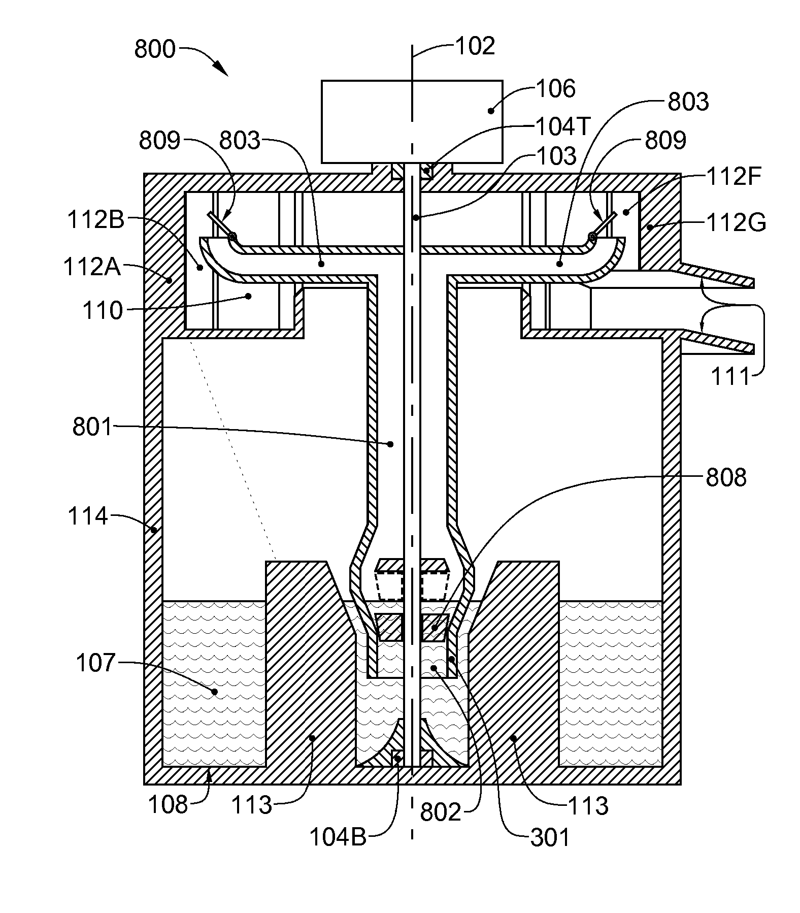
[0039] Referring now to FIG. 8, a third primary embodiment 800 of the new centrifugal pump, which relies entirely on siphoning action to raise the fluid, has a central vertical tube 801 open at a bottom end 802 thereof. The central vertical tube is capped with two or more rotationally balanced horizontal tubes 803, which radiate from the axis of the central vertical tube 801. Each horizontal tube terminates in a 90-degree elbow 804 that is upwardly angled. Alternatively, the horizontal tubes 803 may be replaced with ramped tubes (not shown), that are ramped at least about the diameter thereof. The assembly comprising the vertical tube 801, the horizontal tubes 803 and the 90-degree elbows 804 rotates about the vertical central axis 102 of the vertical tube 801. Fluid 107 being expelled through the horizontal tubes 803 as the assembly spins draws fluid up the central vertical tube 801. This third primary embodiment pump 800 must be primed in order for the pumping action to begin. Thi...


PUM


Abstract

An apparatus for elevating a fluid includes: a pumping member rotatable about a vertical axis, the pumping member having at least one ramped path, the ramped path having a lowermost portion insertable below the surface of a fluid to be elevated, and an uppermost portion that is more distant from the vertical axis than the lowermost portion thereof; a catch chamber surrounding a circular trajectory of the uppermost portion as it rotates about the vertical axis and positioned to receive fluid expelled from the uppermost portion; and a motor coupled to the pumping member for imparting rotational motion to the pumping member about the vertical axis, the motor having sufficient power to generate a centrifugal force that will drive the fluid from the lowermost portion of the ramped path to the uppermost portion and into the catch chamber.

Description

[0001] This application has a priority based on the filing of Provisional Patent Application No. 60 / 737794 on Nov. 17, 2005.BACKGROUND OF THE INVENTION [0002] 1. Field of the Invention [0003] This invention relates to pumps and, more particularly, to centrifugal pumps capable of continuous elevation of massive flows of fluids to higher elevations. [0004] 2. Description of the Prior Art [0005] In the realm of industrial equipment, pumps are indispensable. They are used to raise water from wells, move gases and fluids through pipelines, compress gases, create partial vacuums, pressurize fluids, and for countless other uses. [0006] There are two basic kinds of pumps: mechanical and non-mechanical. Mechanical pumps, which are the most common type, rely on moving parts to generate the pumping action. Non-mechanical, on the other hand, move fluids by means of either electromagnetic force or the force of another fluid such as compressed air. [0007] Most mechanical pumps are driven by a rot...

Claims


Application Information

Patent Timeline
IPC IPC(8): F01D1/36
CPCF04D1/14F04D5/001
Inventor CLEMENT, ROGER B.
Owner CLEMENT ROGER B
Why Eureka
Try Eureka