Piston for a two-stroke engine and a method of making the same

a two-stroke engine and piston technology, applied in the field of two-stroke engine pistons and a method of making the same, can solve the problems of deteriorating dimensional stability of the piston, affecting the quality of the piston, and the piston base cannot be machining in this clamped state, so as to reduce the clamping force, reduce tolerances, and ensure the effect of accuracy

Inactive Publication Date: 2007-05-24
ANDREAS STIHL AG & CO KG
View PDF3 Cites 11 Cited by
  • Summary
  • Abstract
  • Description
  • Claims
  • Application Information

AI Technical Summary

Benefits of technology

[0005] The piston has two opposite-lying planar clamping surfaces on the piston pin bosses. For this reason, the piston can be positioned on a clamping tool and can be gripped thereby. The clamping tool grips the two clamping surfaces at the piston pin boss. In this way, the piston skirt is not significantly deformed in the clamped state of the piston so that the piston skirt can be machined with high accuracy in the clamped state of the piston.
[0014] It is practical that the clamping surfaces of the piston are configured nonsymmetrically to the center plane. The center plane contains the longitudinal center axis of the piston and the longitudinal axis of the bore in the piston pin boss. The clamping tool and the piston are aligned to each other at the nonsymmetry in advance of the clamping of the piston. The piston is made in a pressure die-casting method in advance of the machining operation. The stop surface and the clamping surfaces are made in the pressure die-casting process. The stop surface and the clamping surfaces can be made with sufficiently high accuracy in a pressure die-casting process. In this way, it is possible to completely machine the piston in only one clamping state.

Problems solved by technology

Because of the stop, a machining of the piston base in this clamped state is not possible.
The renewed clamping leads to the situation that additional tolerances in machining result which lead to a deteriorated dimensional stability of the piston.
This leads to greater wall thicknesses of the piston and an increased weight.
Clamping the piston on the inner side of the piston skirt can lead to a deformation of the piston and therefore to a deteriorated dimensional stability of the machined piston skirt.

Method used


Image

  • Piston for a two-stroke engine and a method of making the same
  • Piston for a two-stroke engine and a method of making the same
  • Piston for a two-stroke engine and a method of making the same

Examples


Embodiment Construction

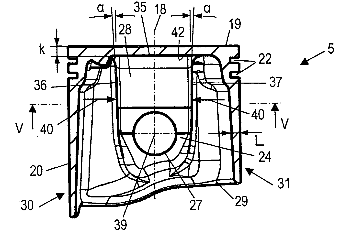
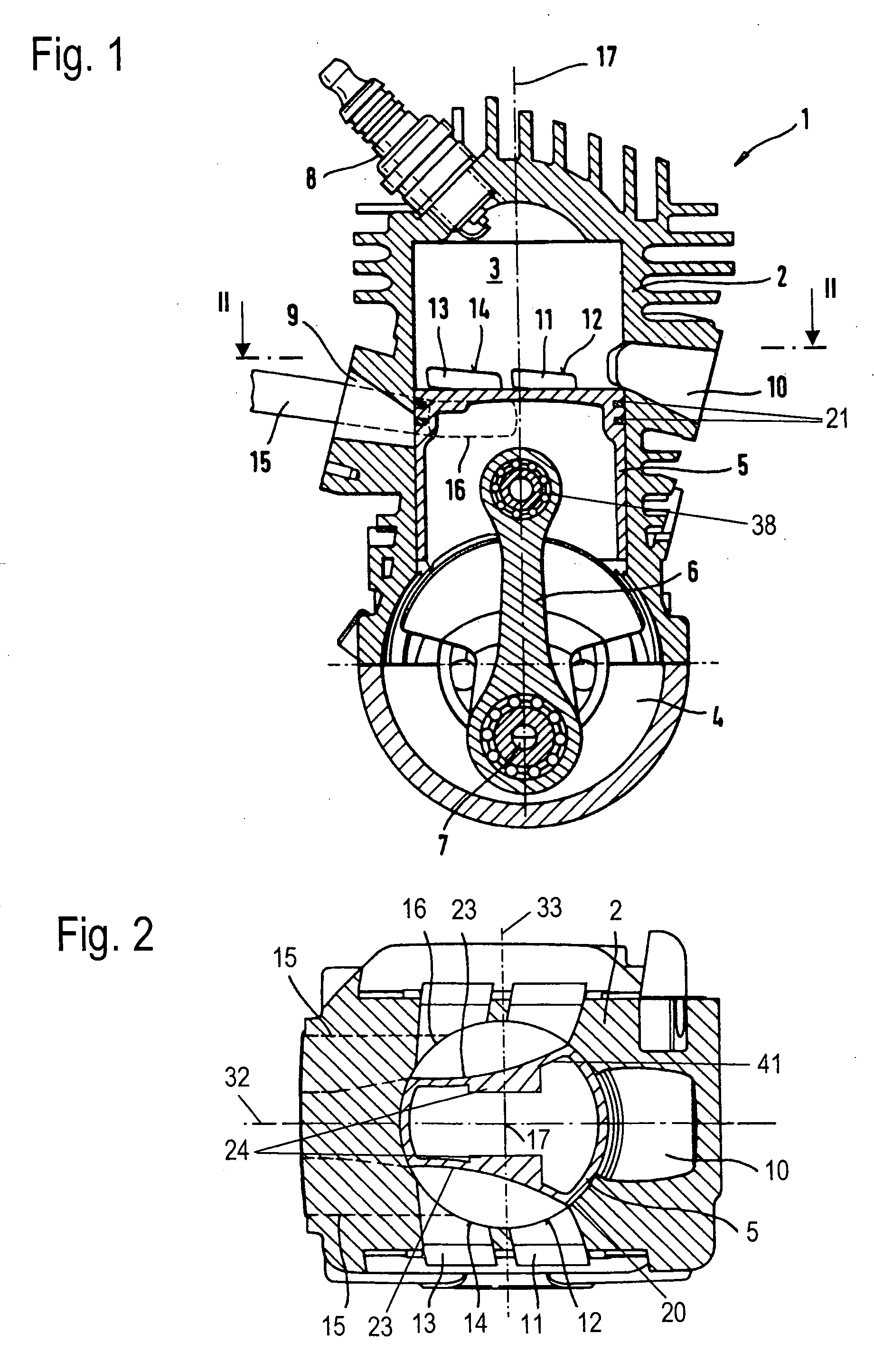
[0023] The two-stroke engine 1 shown in FIG. 1 is provided as a drive motor for a portable handheld work apparatus such as a motor-driven chain saw, a cutoff machine, a brushcutter or the like. The two-stroke engine 1 is configured as a single cylinder engine and has a cylinder 2 wherein a combustion chamber 3 is formed. The combustion chamber 3 is delimited by a piston 5 which is journalled for reciprocal movement in the cylinder 2. The piston 5 drives a crankshaft 7 via a connecting rod 6. The crankshaft 7 is rotatably journalled in a crankcase 4 and functions to drive the work tool of the work apparatus. The connecting rod 6 is attached to the piston 5 via a piston pin 38.

[0024] An intake 9 for an air / fuel mixture opens at the cylinder 2. The intake 9 is slot controlled by the piston 5 and is connected to the crankcase 4 in the region of top dead center of the piston 5. A discharge 10 for exhaust gases leads from the combustion chamber 3. A spark plug 8 projects into the combust...


PUM

PropertyMeasurementUnit
angleaaaaaaaaaa
distanceaaaaaaaaaa
diameteraaaaaaaaaa

Abstract

A piston (5) for a two-stroke engine (1) has a piston base (19) and at least one piston pin boss (24). The piston pin boss (24) has a bore for accommodating a piston pin. At the piston pin boss (24), two mutually opposite-lying planar clamping surfaces (36, 37) are formed. The piston (5) is produced in a pressure die cast process and is thereafter clamped at the clamping surfaces (36, 37) and a stop surface (35). In this clamping state, all machining operations of the piston (5) can be carried out so that a high dimensional stability of the piston (5) results.

Description

CROSS REFERENCE TO RELATED APPLICATION [0001] This application claims priority of German patent application no. 10 2005 055 787.2, filed Nov. 23, 2005, the entire content of which is incorporated herein by reference. BACKGROUND OF THE INVENTION [0002] U.S. Pat. No. 3,460,239 discloses a piston having a piston base and two piston pin bosses. The piston pin bosses each have a bore for the piston pin. A casting process is provided for manufacturing the piston. Thereafter, the piston is machined in a machining method. For this purpose, the piston is clamped at its inner side in two mutually spaced planes. In order to position the piston in the direction of its longitudinal center axis, the piston is pressed with a pressure piece against a stop arranged on the outer side of the piston base. The pressure piece is arranged on the inner side of the piston base. Because of the stop, a machining of the piston base in this clamped state is not possible. The piston must be clamped anew for mach...

Claims


Application Information

Patent Timeline
Patent Type & Authority Applications(United States)
IPC IPC(8): F16J1/04
CPCB23B31/16275B23B2215/24B23B2215/245B23P15/10B25B5/147F02F3/24
Inventor HAUSSERMANN, SIEGFRIEDSCHNAITHMANN, KLAUSKREUZBERGER, WERNERSCHLOSSARCZYK, JORGGEYER, WERNER
Owner ANDREAS STIHL AG & CO KG
Why Eureka
Try Eureka