X-ray detector and method

a detector and detector technology, applied in the field of x-ray detectors, can solve the problems of reducing the size of the detector envelope, reducing the detection efficiency of the detector, so as to prevent outgassing

Inactive Publication Date: 2007-05-24
OXFORD INSTUMENTS ANALYTICAL LIMITED
View PDF11 Cites 16 Cited by
  • Summary
  • Abstract
  • Description
  • Claims
  • Application Information

AI Technical Summary

Benefits of technology

[0017] a getter material, applied as a coating to the one or more internal surfaces, for absorbing gaseous species present

Problems solved by technology

This degeneration in the vacuum eventually leads to detector failure or at least some loss in performance.
This can be achieved with small vacuum pumps like ion getter pumps although these are disadvantageous because they are costly, bulky, require a power supply and need to be kept on all the time.
Furthermore, in order to “getter” sufficiently large quantities of gas, such NEG getters need to have a large surface area and can be bulky.
This can present a dimensional size problem and hence lead to an increased size for the detector envelope and even the adoption of an unconventional detector envelope outline.
Space constraints in these machines (that is, small vacuum chambers) necessitate the use of narrow tubes to position the x-ray sensor as close as possible to the source of x-ray generation.
Unfortunately physical size constraints limit the size of the getter 310 to be placed in the “body” pa

Method used


Image

  • X-ray detector and method
  • X-ray detector and method
  • X-ray detector and method

Examples


Embodiment Construction

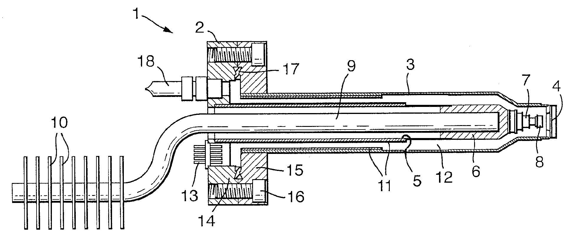
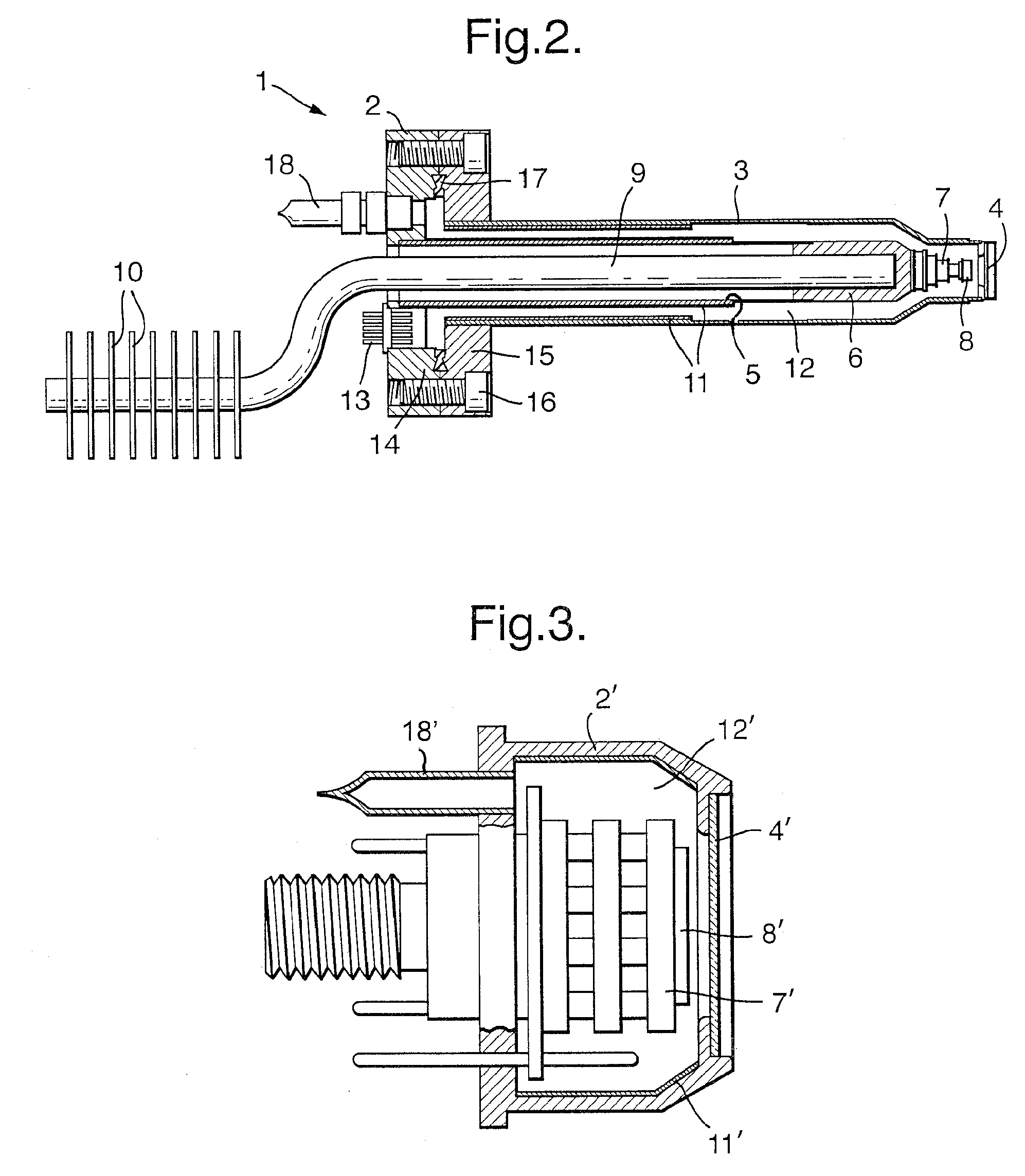
[0042] A first example of an x-ray detector 1 according to the invention is shown in FIG. 2, which is a view partly in section. The detector 1 has a body 2 to which is coupled an elongate cylindrical outer tube 3. At one end of the tube 3, distal from the body 2, an x-ray window 4 is provided, this window being capable of withstanding a pressure differential across its surface, for example an external pressure of about 1 bar on one side and less than 1×10⁻³ mbar on the other. The window is substantially transparent to x-rays. Within the elongate tube 3 a second, inner tube 5 is located, this being of reduced diameter (defining a space there between) and located coaxially with respect to the outer tube. The inner tube 5 terminates within the outer tube and is terminated by an end piece 6 which seals the inner environment within the outer tube (that is, the space between the outer and inner tubes), from the inner environment within the inner tube 5. Each of the tubes 3,5 may be fabric...


PUM


Abstract

We provide an x-ray detector having a housing with one or more internal surfaces defining an internal volume. The housing is adapted in use to contain a vacuum within the internal volume. An x-ray sensor is located within the internal volume of the housing. A window, located within the housing, is adapted to permit the passage through the window of x-rays to be detected from the external environment to the sensor. A getter material is applied as a coating to the one or more internal surfaces, for absorbing gaseous species present within the vacuum and for substantially preventing outgassing from the parts of the walls coated by the getter material.

Description

RELATED APPLICATIONS [0001] This application claims the benefit of U.K. Application No. 0523838.1, filed Nov. 23, 2005. This application is herein incorporated in its entirety by reference. FIELD OF THE INVENTION [0002] The present invention relates to an x-ray detector for use for example in the field of x-ray analysis of materials. A method of making such a detector is also disclosed. BACKGROUND OF THE INVENTION [0003] Sealed vacuum enclosures are desirable in x-ray detectors to keep the x-ray sensor surfaces clean, to reduce the thermal load on a cooled x-ray sensor and to minimise x-ray absorption along the x-ray path length. [0004] Vacuum levels of less than 1×10⁻³ mbar are used to minimise the above effects on the x-ray sensor. It is a known fact that a sealed volume under vacuum will gradually loose the vacuum due to outgassing of internal surfaces, leakage from outside the evacuated envelope and permeation of gases through the solid envelope walls. This degeneration in the v...

Claims


Application Information

Patent Timeline
IPC IPC(8): G01T1/24
CPCH01J2237/2442G01T1/244
Inventor BHADARE, SANTOKH SINGH
Owner OXFORD INSTUMENTS ANALYTICAL LIMITED
Why Eureka
Try Eureka