Ion implanter and ion implantation control method thereof

a technology of ion implanter and control method, which is applied in the direction of electrical equipment, nuclear engineering, electric discharge tubes, etc., can solve the problems of sudden variation of ion beam current, inability to correct characteristic data of ion implanter, and non-uniform amount of ions implanted in a mechanical scan direction, etc., to achieve uniform dose, suppress particle generation as much, and avoid deterioration in wafer processability

Inactive Publication Date: 2007-05-24
PANASONIC CORP
View PDF1 Cites 18 Cited by
  • Summary
  • Abstract
  • Description
  • Claims
  • Application Information

AI Technical Summary

Benefits of technology

[0016] The present invention is made to solve the aforementioned problems, and it is therefore an object of the present invention to provide an ion implanter capable of keeping dose uniformity at a good state without deterioration in wafer processability and, also, capable of suppressing generation of particles as much as possible even when an ion beam state changes due to a change in state of the ion implanter every moment over a long operation period, and an ion implantation control method thereof.

Problems solved by technology

However, in some cases, an amount of ions implanted in a wafer becomes nonuniform in a mechanical scan direction due to a characteristic of an ion implanter, and other reasons.
In the ion implanter and the ion implantation method that are well-known, however, the following problems arise.
However, if the ion implanter is operated for a long period of time, an ion beam current suddenly varies due to a change in state of the ion implanter during the ion implantation treatment in many cases.
If the sudden variation of the ion beam current occurs, the characteristic data of the ion implanter cannot be corrected.
In addition, if the ion beam current suddenly varies upon implantation of ions in a wafer having a characteristic to be measured, the characteristic data of the ion implanter is corrected on the basis of the characteristic of the wafer; therefore, there is a possibility that dose uniformity becomes poor.
However, if a range of the set value is too narrow, there is a fear that a wafer processability deteriorates.
In contrast, if such a range is too wide, dose uniformity becomes poor, leading to the same adverse result as the aforementioned description.
This method can not be applied in such a case.
In addition, if the acceleration voltage is allowed to drop at a later stage like a high current ion implanter, there is a possibility that an increase in energy contamination is caused.
Upon maintenance of the ion implanter, an orbit of the ion beam disadvantageously deviates due to changes in state of the ion implanter, such as erroneous attachment of an exchanged ion source, a chipped slit in an extraction electrode, and adhesion of deposits, so that an area, irradiated with the ion beam, of a component located on the orbit of the ion beam is enlarged.
As a result, particles are easily generated, leading to deterioration in yield of a semiconductor device product and reduction in operating time of the ion implanter.

Method used


Image

  • Ion implanter and ion implantation control method thereof
  • Ion implanter and ion implantation control method thereof
  • Ion implanter and ion implantation control method thereof

Examples


first embodiment

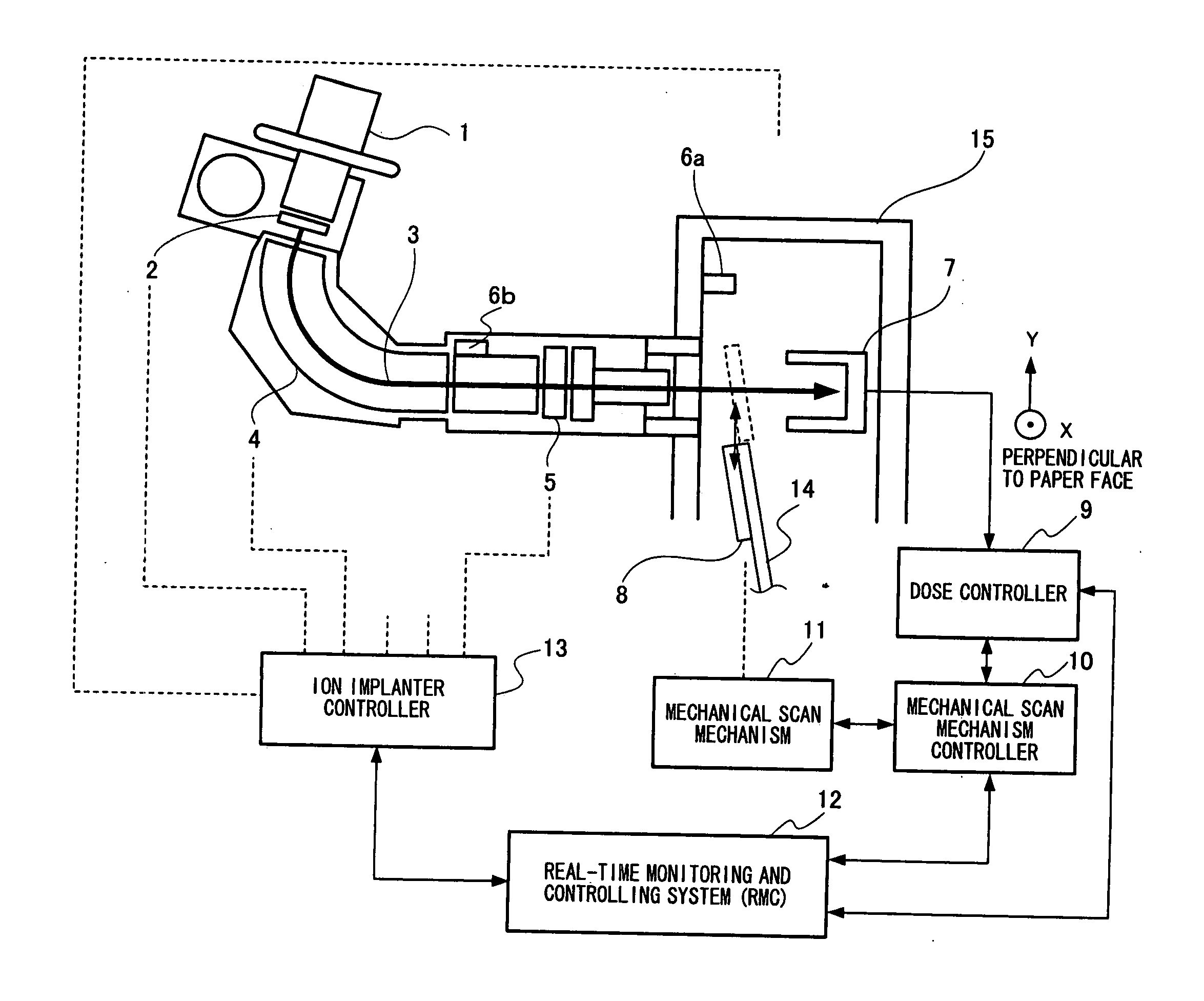
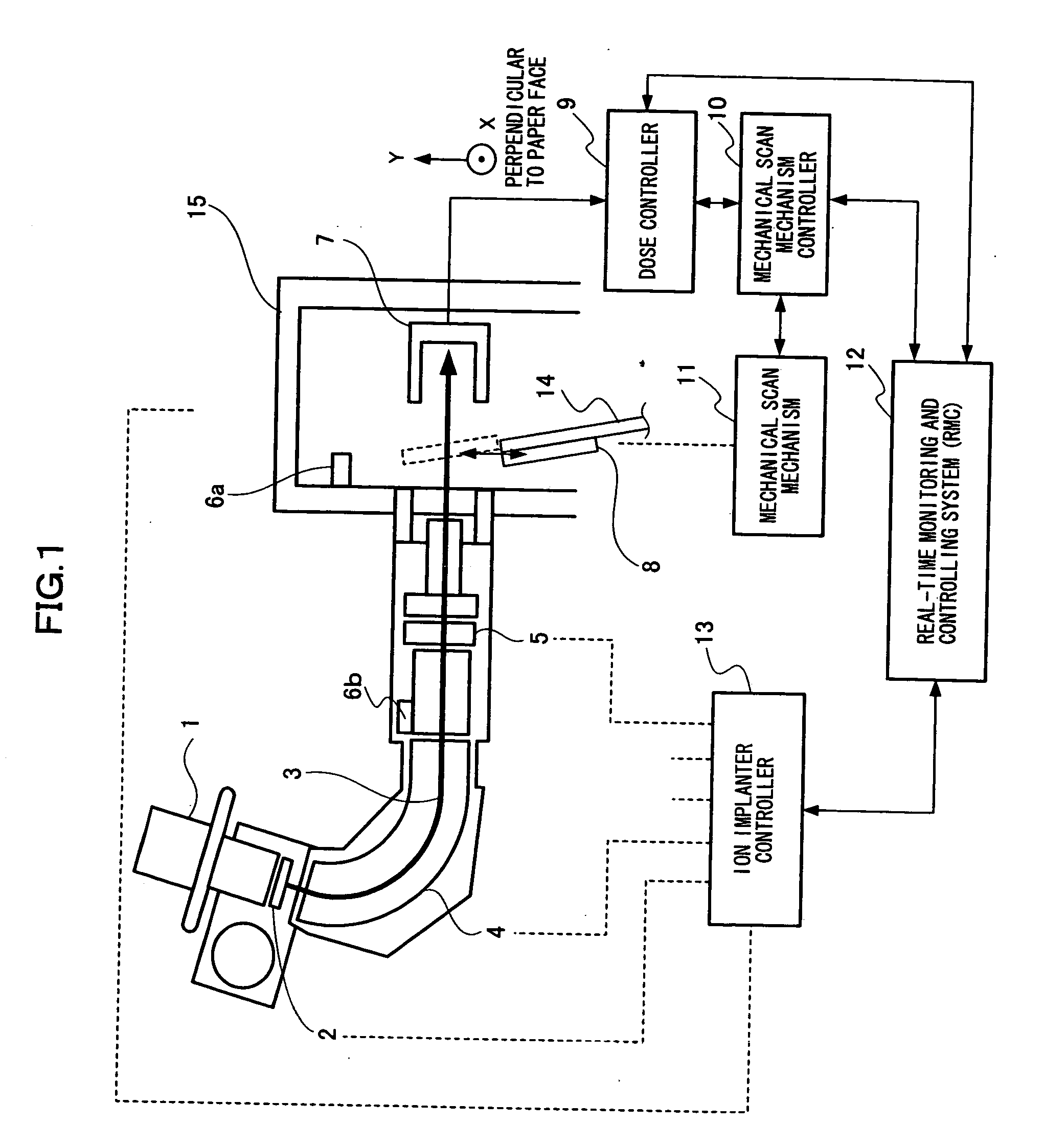
[0037]FIG. 1 schematically illustrates a configuration of an ion implanter according to a first embodiment of the present invention.

[0038] As illustrated in FIG. 1, the ion implanter includes: an ion source 1; an extraction electrode (an extraction accelerating section) 2 for extracting an ion beam 3 from the ion source 1; a mass analyzing section 4 for acquiring desired ions of the ion beam 3 extracted by the extraction electrode 2; an aperture (an opening) 5 having a function of removing redundant ions and particles from an ion beam outputted from the mass analyzing section 4 so that such ions and particles do not reach a (semiconductor) wafer 8; a particle monitor (a particle counting section) 6a for measuring the number of particles in an end-station 15; a particle monitor (a particle counting section) 6b arranged on an upstream side of the aperture 5 to measure the number of particles; a dose Faraday cup 7 provided in the end-station 15 to receive the ion beam 3 upon implantat...

second embodiment

[0057] Description will be given of a second embodiment of the present invention with reference to FIGS. 1 to 4 and 6 to 8. It is to be noted that a whole configuration of an ion implanter in the second embodiment is similar to that in the first embodiment; therefore, the same components are denoted by the same symbols and specific description thereof will not be given here.

[0058] In the first embodiment, when the ion beam current varies frequently, there is a fear that the operating ratio reduces due to the stoppage of processing by the ion implanter interlock. Accordingly, this embodiment realizes an ion implanter capable of keeping dose uniformity at a good state by a correction function even when an ion beam current varies.

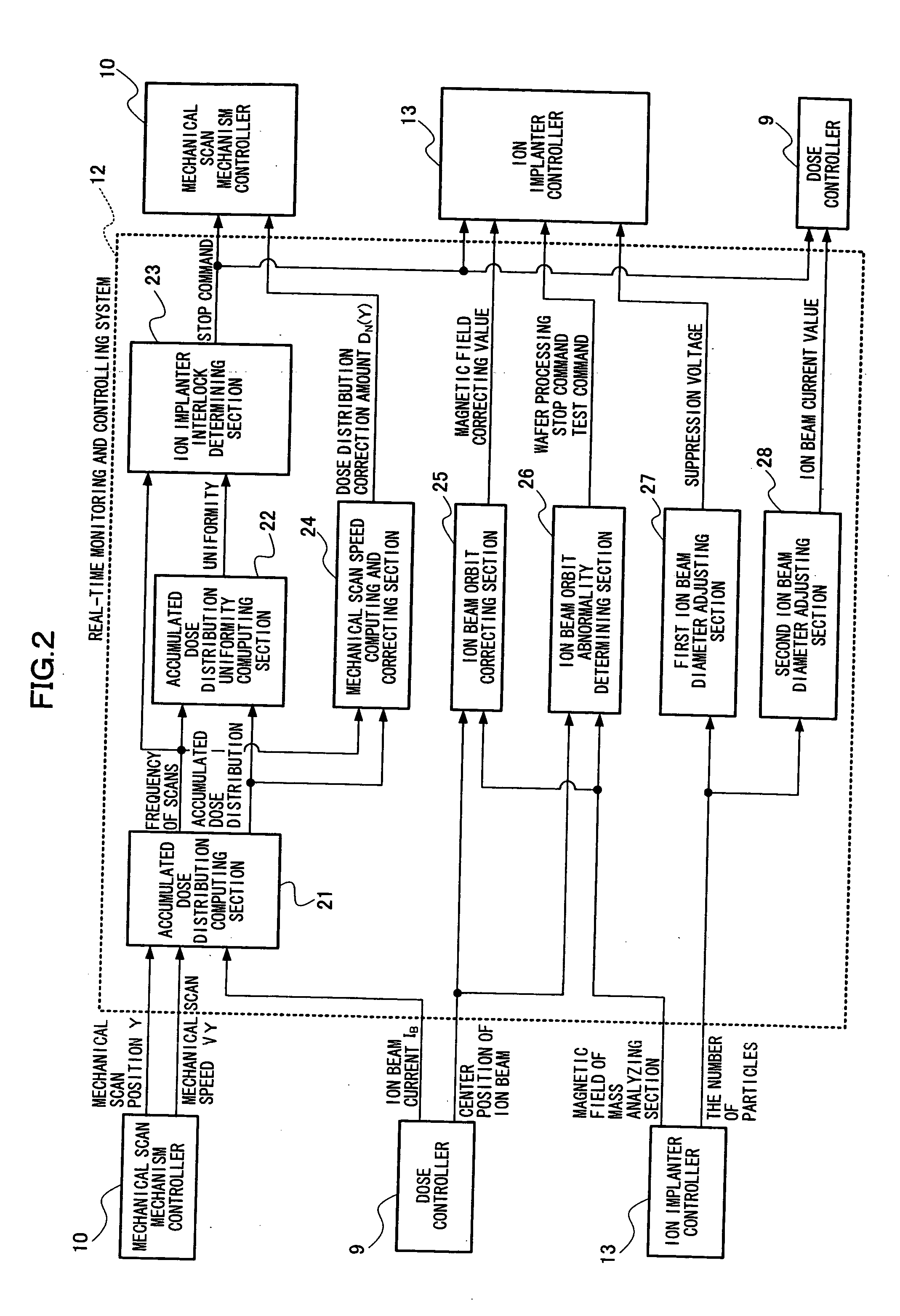
[0059] As illustrated in FIG. 2, the real-time monitoring and controlling system 12 includes a mechanical scan speed computing and correcting section 24.

[0060] The mechanical scan speed computing and correcting section 24 obtains a correction amount for cor...

third embodiment

[0072] Description will be given of a third embodiment of the present invention with reference to FIGS. 1, 2, 9 and 10. It is to be noted that a whole configuration of an ion implanter in the third embodiment is similar to that in the first embodiment; therefore, the same components are denoted by the same symbols and specific description thereof will not be given here.

[0073] As illustrated in FIG. 2, the real-time monitoring and controlling system 12 accepts an input of a magnetic field applied in the mass analyzing section 4 from the ion implanter controller 13, and an input of a measured center position of the ion beam 3 in the Y direction (the center position of the ion beam 3 in the Y direction) from the dose controller 9.

[0074] As illustrated in FIG. 2, the real-time monitoring and controlling system 12 includes an ion beam orbit correcting section 25 and an ion beam orbit abnormality determining section 26.

[0075] The ion beam orbit correcting section 25 obtains a correctio...


PUM


Abstract

An ion implanter is provided with a system for monitoring parameters of the ion implanter in real time to control respective components in the ion implanter. This system is allowed to have a function of calculating an accumulated dose distribution during ion implantation treatment and correcting a mechanical scan speed of a wafer holding section in a Y direction so as to render an accumulated dose uniform, a function of changing a magnetic field of a mass analyzing section to thereby control a center position of an ion beam, and a function of varying a suppression voltage of an aperture and an ion beam current to control a diameter of the ion beam.

Description

BACKGROUND OF THE INVENTION [0001] (1) Field of the Invention [0002] The present invention relates to an ion implanter for implanting ions in a semiconductor wafer, and anion implantation control method thereof. In particular, the present invention relates to an ion implanter capable of improving dose uniformity and suppressing generation of contaminated particles on a wafer, and an ion implantation control method thereof. [0003] (2) Description of the Related Art [0004] In an ion implanter, a technique for improving dose uniformity and a technique for reducing the number of particles are fundamental techniques, and various modifications have been made heretofore. [0005] First, description will be given of the technique for improving dose uniformity. [0006] An ion implanter mainly includes an ion source for generating ions, an extraction electrode (an accelerating section), a mass analyzing section for acquiring desired ions, an accelerating / decelerating section for acquiring desire...

Claims


Application Information

Patent Timeline
Patent Type & Authority Applications(United States)
IPC IPC(8): H01J37/08
CPCH01J37/05H01J37/304H01J37/3045H01J37/3171H01J2237/20228H01J2237/20278H01J2237/30455H01J2237/30477H01J2237/30488H01J2237/31703
Inventor YASUDA, SATOSHI
Owner PANASONIC CORP
Why Eureka
Try Eureka