Piezoelectric filter
- Summary
- Abstract
- Description
- Claims
- Application Information
AI Technical Summary
Benefits of technology
Problems solved by technology
Method used
Image

Examples
first embodiment
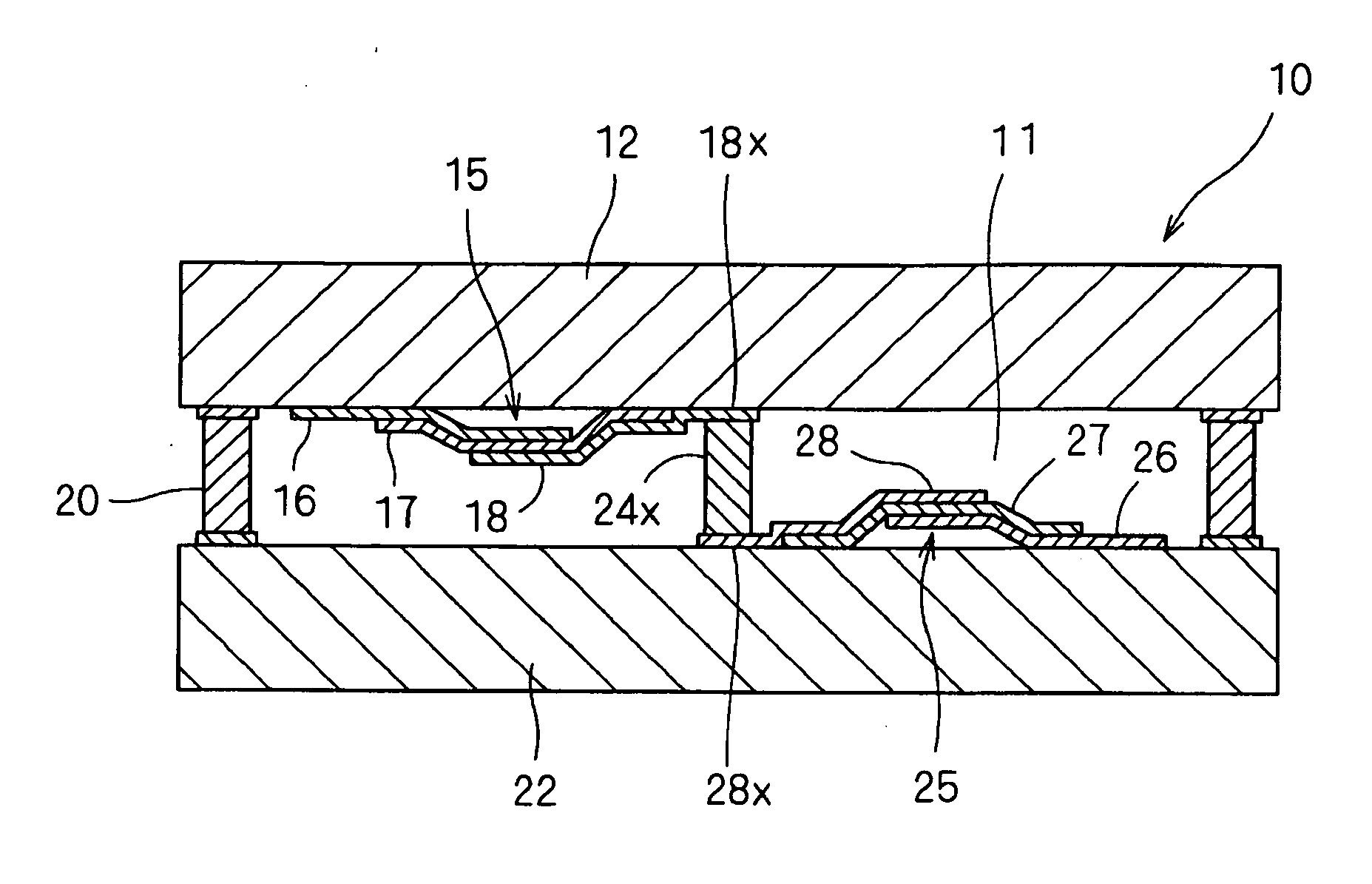
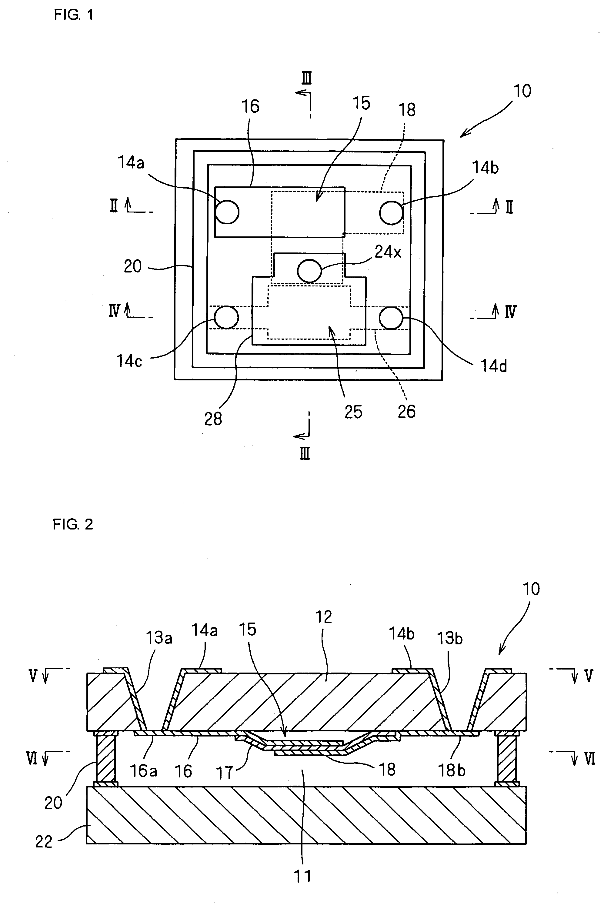
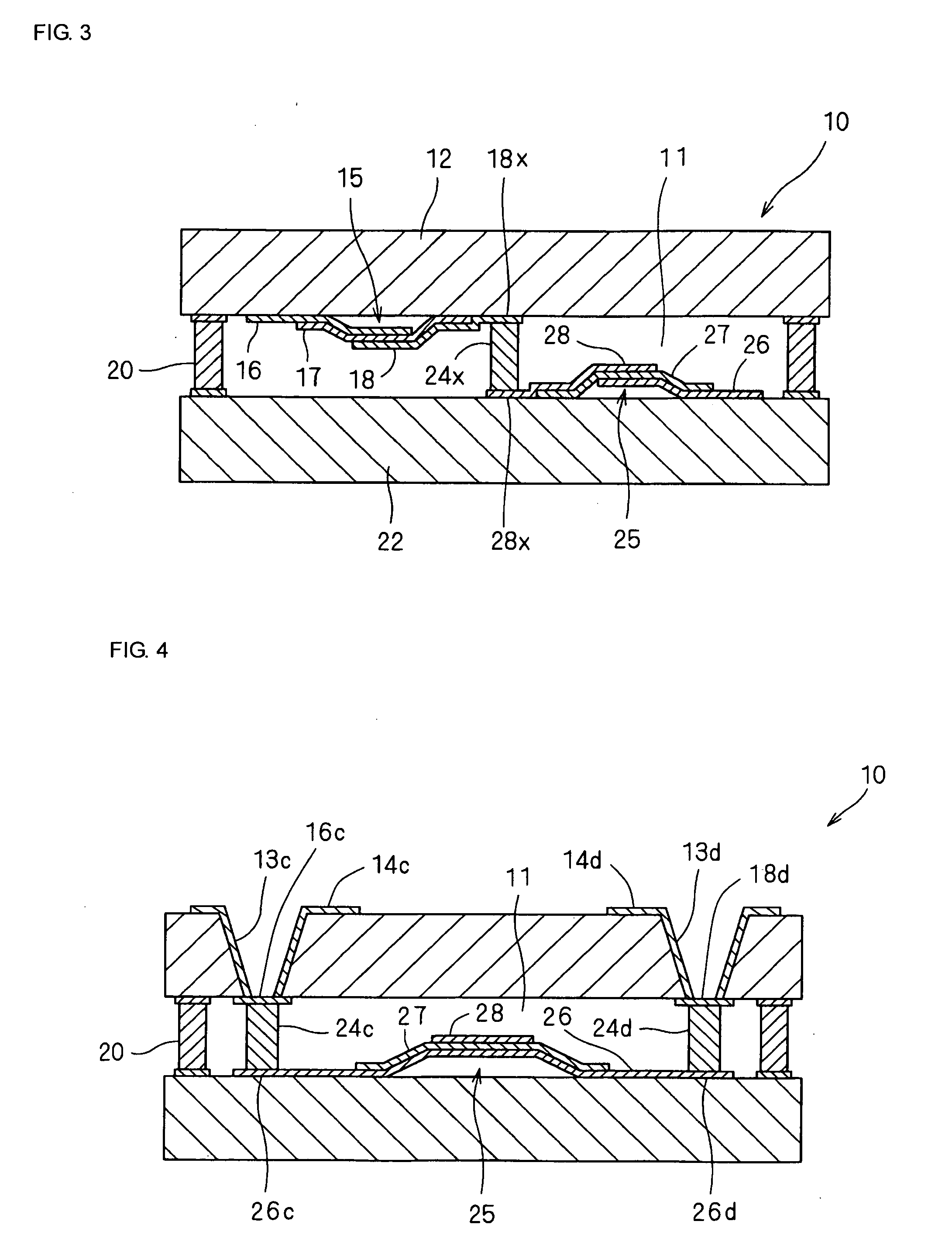
[0099]FIG. 1 is a perspective view of a piezoelectric filter 10 according to a first embodiment. FIG. 2 is a cross-sectional view taken along line II-II in FIG. 1. FIG. 3 is a cross-sectional view taken along line III-III in FIG. 1. FIG. 4 is a cross-sectional view taken along line IV-IV in FIG. 1. FIG. 5 is a perspective view of substrate 12. FIG. 6 is a cross-sectional view showing the other substrate 22. FIG. 7 is an enlarged view of a connecting layer. FIG. 8 is a schematic circuit diagram of a piezoelectric filter 10.
[0100] As shown in FIG. 8, the piezoelectric filter 10 is a ladder filter in which a series resonator 15 and a parallel resonator 25 are connected in the form of an L-shape.
[0101] As shown in FIGS. 2 to 4, broadly speaking, the substrate 12 including the series resonator 15 is bonded to the substrate 22 such that a main surface having the series resonator 15 faces a main surface having the parallel resonator 25 and such that the substrate 12 is remote from the su...
second embodiment
[0119]FIG. 9 is a perspective view of a piezoelectric filter 40 according to a second embodiment. FIG. 10 is a cross-sectional view. FIG. 11 is a longitudinal sectional view taken along line XI-XI in FIG. 9. FIG. 12 is a longitudinal sectional view taken along line XII-XII in FIG. 9. FIG. 13 is a schematic circuit diagram of the piezoelectric filter 40.
[0120] As shown in FIG. 13, the piezoelectric filter 40 is a lattice filter in which series resonators 45a to 45d and parallel resonators 55a to 55d are connected in the form of a lattice.
[0121] As shown in FIGS. 9 to 12, in the piezoelectric filter 40, a substrate 42 having the series resonators 45a to 45d is bonded to a substrate 52 having the parallel resonators 55a to 55d with a connection pattern 50 such that a main surface having the resonators 45a to 45d faces a main surface having the resonators 55a to 55d and such that the substrate 42 is remote from the substrate 52, the resonators 45a to 45d and 55a to 55d being sealed in...
third embodiment
[0127]FIG. 14 is a sectional view of a piezoelectric filter 60 according to a third embodiment.
[0128] The piezoelectric filter 60 includes substrates 62 and 72 having resonators (SAW resonators) 66 and 76 using surface acoustic waves. That is, interdigital transducer (IDTs) are formed on the piezoelectric substrate 62 and 72. An external electrode 64, a connection pattern 70, a connecting layer 74, and the like are the same as in other embodiments.
[0129] In the known surface acoustic wave device, a piezoelectric substrate having an anisotropic linear expansion coefficient is used. When a lid substrate is bonded at a wafer level, the same piezoelectric substrate must be used as the lid substrate. However, use of an expensive piezoelectric substrate as a mere structural component (lid substrate) increases costs. Thus, a surface acoustic wave element is packaged with a resin having less hermeticity and less strength.
[0130] In the piezoelectric filter 60 according to third embodiment...
PUM
 Abstract
Description
Claims
Application Information
 - Generate Ideas
- Intellectual Property
- Life Sciences
- Materials
- Tech Scout
- Unparalleled Data Quality
- Higher Quality Content
- 60% Fewer Hallucinations
Browse by: Latest US Patents, China's latest patents, Technical Efficacy Thesaurus, Application Domain, Technology Topic, Popular Technical Reports.
© 2025 PatSnap. All rights reserved.Legal|Privacy policy|Modern Slavery Act Transparency Statement|Sitemap|About US| Contact US: help@patsnap.com