Novel jack form LED lamp package and caddy

Inactive Publication Date: 2007-05-24
TRUXES WILLIAM W
View PDF21 Cites 25 Cited by
  • Summary
  • Abstract
  • Description
  • Claims
  • Application Information

AI Technical Summary

Benefits of technology

[0029] It is another object and advantage of the jacklamp, that when a powered port or a power adapter-charger is unavailable, it can be used on a portable, powered, storage and transportation accessory device, hereinafter referred to as a jacklamp caddy, to provide portable hand held task lighting.
[0030] It is another object and advantage of the jacklamp, that it can be used with the jacklamp caddy and a cable to provide portable extended task lighting.
[0031] It is another object and advantage of the jacklamp, that it can be used with the jacklamp caddy to test a cables power circui

Problems solved by technology

Illuminated displays and keyboards have reduced the utility of bus pluglamps to lighting nearby objects (i.e., confined to within the half meter neck length, of a receiving computer port).
Bus pluglamps may be received by these power adapter-chargers, but are limited again t

Method used


Image

  • Novel jack form LED lamp package and caddy
  • Novel jack form LED lamp package and caddy

Examples


embodiment 100

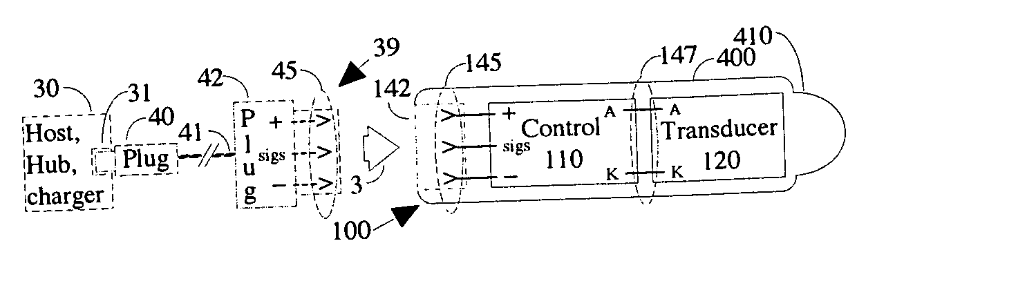
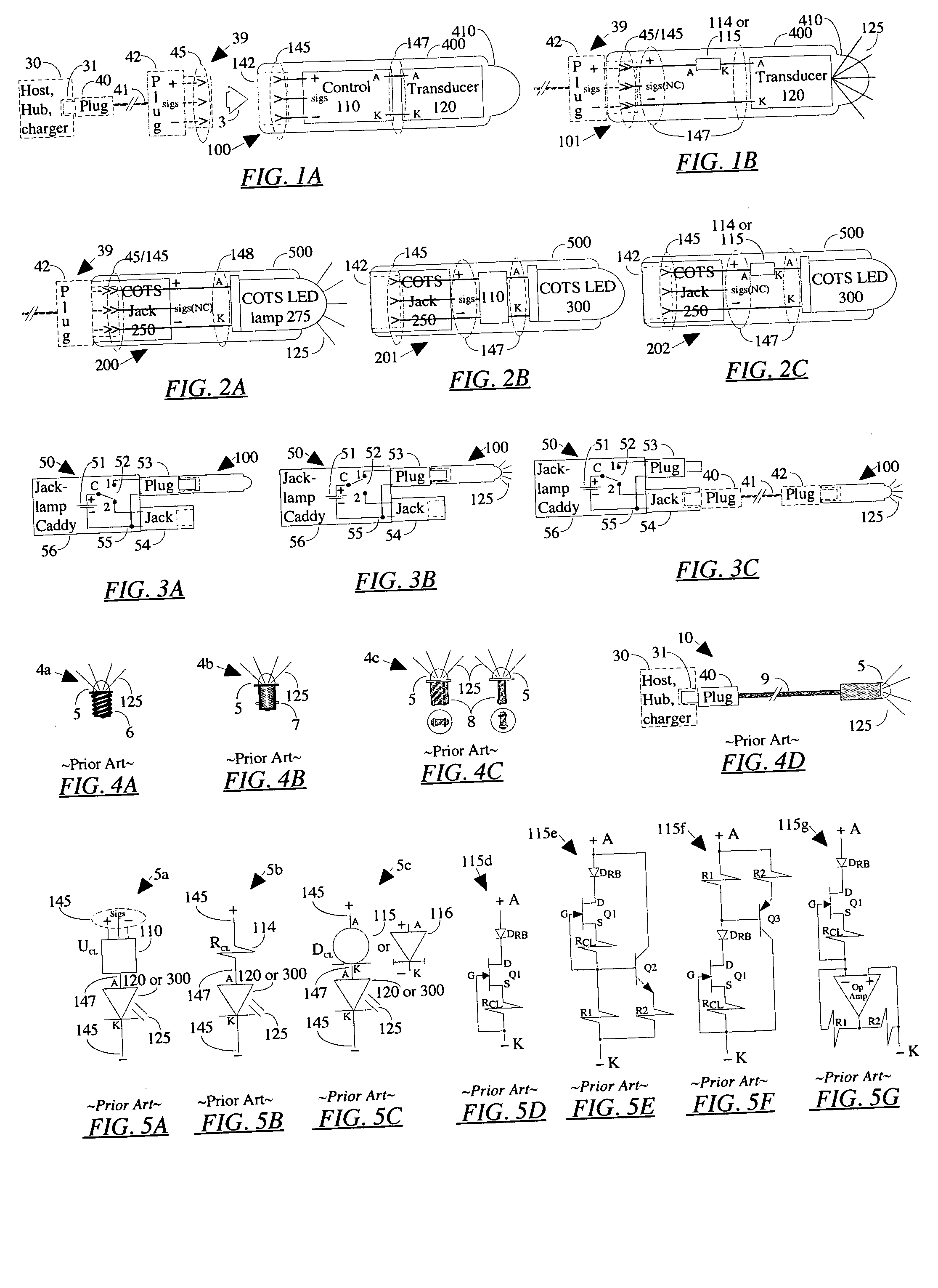
[0058]FIG. 1A illustrates the jacklamps preferred cast package embodiment 100 about to be connected with a powered bus cable 39.

[0059] The preferred cast embodiment jacklamp 100 comprises a component encapsulating, transparent, cast-polymer package 400 having integral cast optics 410 and a recess 142 formed to receive (from direction of arrow 3) the downstream plug 42 of a powered bus cable 39; a plurality of jack contacts 145 in the packages 400 plug recess 142 to make electrical connections between the downstream plug 42 contacts 45 (.plus., . minus., and signals) and the integrated circuit electrical energy control die 110; a lead frame 147 (i.e. a metal skeletal structure) utilized to electrically connect, cool by thermal conduction, and support the transducer die 120 and its control die 110; a control die 110 to (when powered) actively control the electrical energy to at least one transducer die 120 via the lead frame 147; and at least one electrical energy to radiant energy tr...

embodiment 101

[0067]FIG. 1B illustrates the jacklamps second preferred cast package embodiment 101 connected 45 / 145 (i.e. plug 42 contacts 45 to jacklamp 101 contacts 145), to a powered bus cable 39, thereby emitting radiant energy 125.

[0068] This jacklamp 101 differs from the previous jacklamp 100 only in the method of current control used to drive the transducer 120.

[0069] Instead of using variable, bus controlled current via IC 110 (circuit 5a shown in FIG. 5A), this jacklamp 101 uses fixed current control provided by either a current limiting (or ballast) resistor 114 (circuit 5b shown in FIG. 5B) or a current limiting diode (CLD) 115 (circuit 5c shown in FIG. 5C). CLDs are also known as constant current diodes (CCD) and have an alternate schematic symbol 116.

[0070] It is known in the art that EERE transducers 120 are best driven by a fixed constant current source. Constant current drives, to varying degrees, automatically compensate for variations of supply voltage, component parameters an...

embodiment 200

[0073]FIG. 2A illustrates the jacklamps preferred Commercial Off The Shelf (COTS) embodiment 200 connected 45 / 145 (i.e. plug 42 contacts 45 to jacklamp 200 contacts 145), to a powered bus cable 39, thereby emitting radiant energy 125.

[0074] The preferred COTS embodiment jacklamp 200 comprises a molded polymer package 500 encapsulating at least two components; a COTS jack 250 to receive the downstream plug 42 of a powered bus cable 39 to make electrical connections 45 / 145 between the downstream plug 42 contacts 45 (.plus. and .minus.), the jack 250 contacts 145 (.plus. and .minus.) and the leads 148 (A and K) of a COTS LED lamp 275; and at least one COTS LED lamp 275 to emit radiant energy 125.

[0075] The package 500 molding material selection and fabrication, is well understood in the art, and accordingly will not be described further herein.


PUM


Abstract

A unique LED lamp package is disclosed that can receive a plug (42), make electrical connection in a circuit (39) and cast radiant energy (125) (UV, visible, IR or a combination) in at least one direction rendering objects in that direction visible, hereinafter referred to as a jacklamp (100, 101, 200, 201, 202). In one embodiment (100) the components of a jacklamp, consisting of at least one LED die (120), a controller (110), and an interconnecting lead frame (147), are encapsulated in transparent polymer (400) shaped with a recess (142) to receive a plug (42) and direct radiation (125). In another jacklamp embodiment (201), a commercial off the shelf (COTS) jack (250), a controller (110), and at least one COTS LED (300), are interconnected by a lead frame (147) and encased in a molded polymer package (500). Plug a compatible bus cable into a jacklamp and direct or observe its illumination. A jacklamp will task light areas limited only by the cable length, provide indication of the health of a cable circuit, and identify a single cable in a bundle. In the absence of another bus powering device, the caddy, provides a means of independently powering a jacklamp or a prior art bus pluglamp, besides providing convenient and secure transportation and storage.

Description

CROSS-REFERENCE TO RELATED APPLICATIONS [0001] This application claims the benefit of provisional patent application Ser. No. 60 / 630,497, filed 2004 Nov. 11 by the present inventor.FEDERALLY SPONSORED RESEARCH [0002] Not Applicable REFERENCE TO A MICROFICHE APPENDIX [0003] Not Applicable BACKGROUND OF THE INVENTION [0004] This invention relates in general to Light Emitting Diode (LED) lamp packages, and in particular to a novel jack form LED lamp illuminator package, hereinafter referred to as a jacklamp, and a caddy for it. [0005] A LED package is known in the trade to consist of, at least one electrical energy to radiant energy transducer die (e.g. a LED, an organic LED (OLED) or laser diode (LD)), a lead frame (i.e. a metal skeletal structure utilized to electrically connect, cool by thermal conduction, and support the transducer die.) and a cast transparent polymer encapsulant, forming the device enclosure and its integrated optics. When provided with externally controlled elect...

Claims


Application Information

Patent Timeline
IPC IPC(8): H01R3/00
CPCF21V23/06F21V33/0052F21Y2101/02F21Y2115/10
Inventor TRUXES, WILLIAM W.
Owner TRUXES WILLIAM W
Why Eureka
Try Eureka