Method and apparatus for processing and injecting drill cuttings

a drilling cutting and injection technology, applied in the direction of drilling casings, drilling pipes, borehole/well accessories, etc., can solve the problems of mud contaminant the environment, process, transportation, and disposal, and achieve the effect of reducing space requirements, reducing personnel, and reducing downtime and operating costs

Inactive Publication Date: 2007-05-31
REDDOCH SR JEFFREY A
View PDF9 Cites 3 Cited by
  • Summary
  • Abstract
  • Description
  • Claims
  • Application Information

AI Technical Summary

Benefits of technology

[0009] It can be seen that open, fluidized containers allow easy access to the grinding pumps and visual inspection of the cuttings slurry. Further, the improved drill

Problems solved by technology

While the drilling fluid is necessary to the drilling operation, the shear nature of its formulation makes the mud a contaminant to the environment.
Yet problems still persist that cause production delays due to an inability to process, transport, and dispose of the drill cuttings and economically recover and handle the residual drilling fluid contaminates.
These problems are present in virtua

Method used


Image

  • Method and apparatus for processing and injecting drill cuttings
  • Method and apparatus for processing and injecting drill cuttings
  • Method and apparatus for processing and injecting drill cuttings

Examples


Embodiment Construction

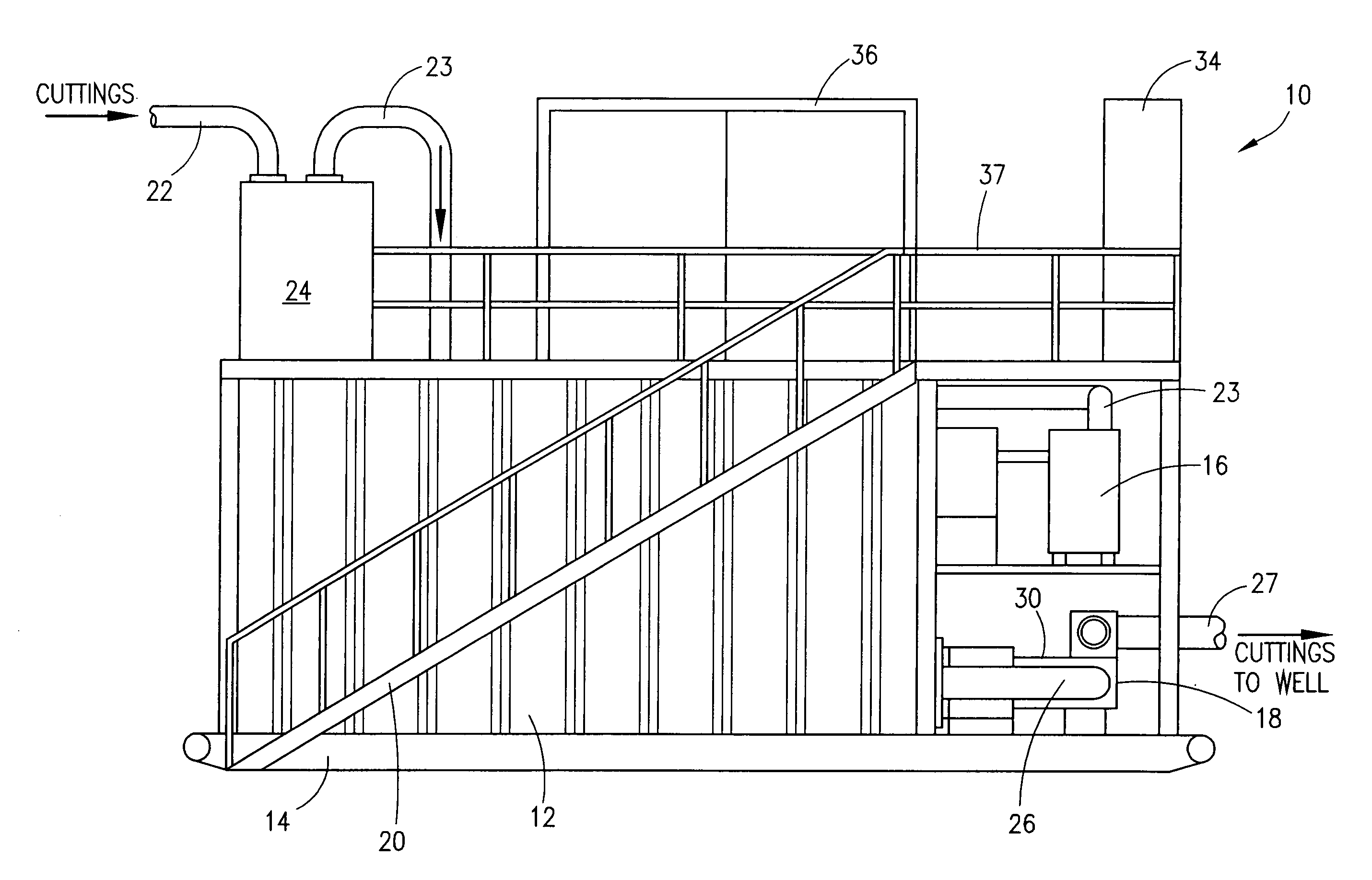
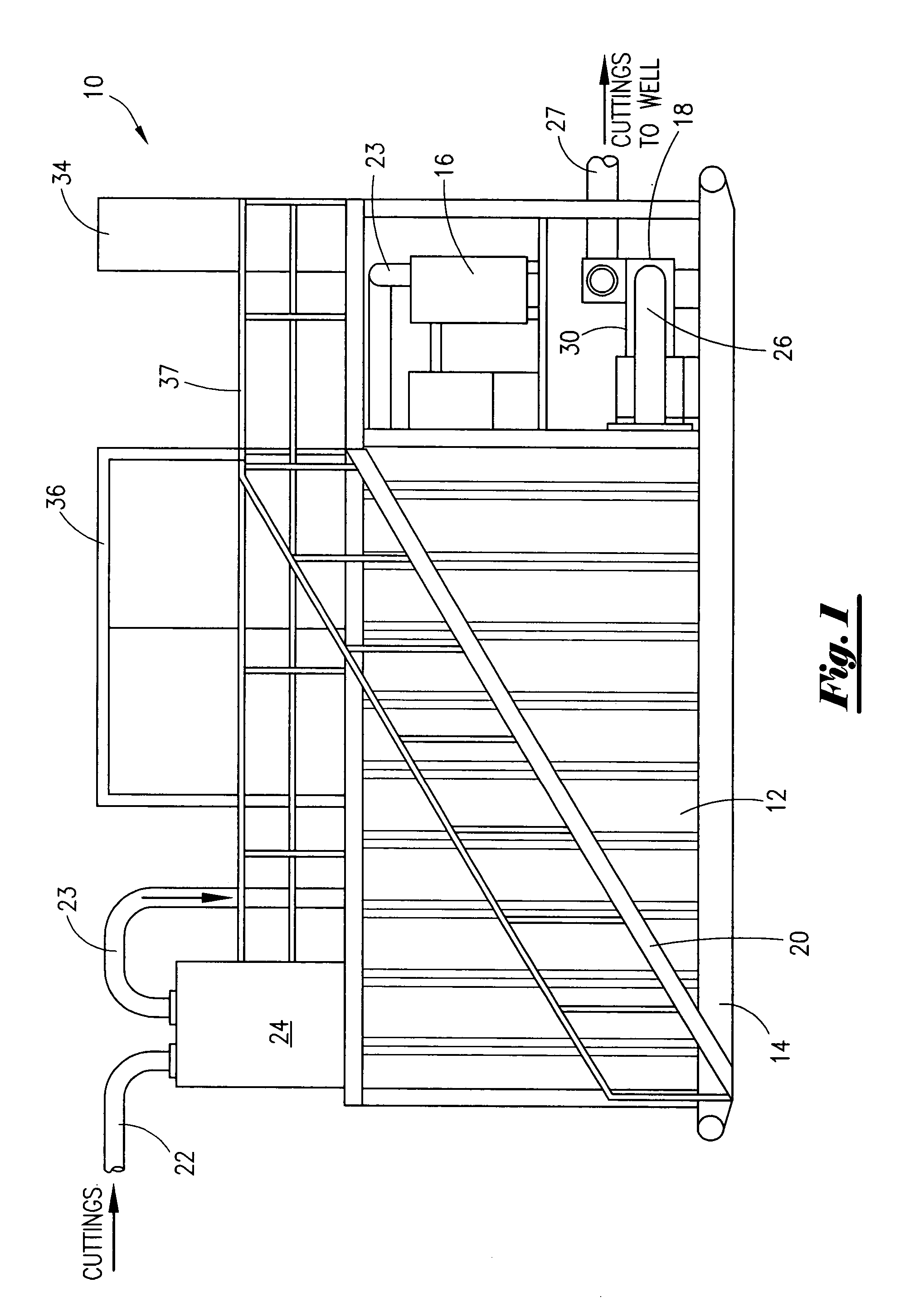
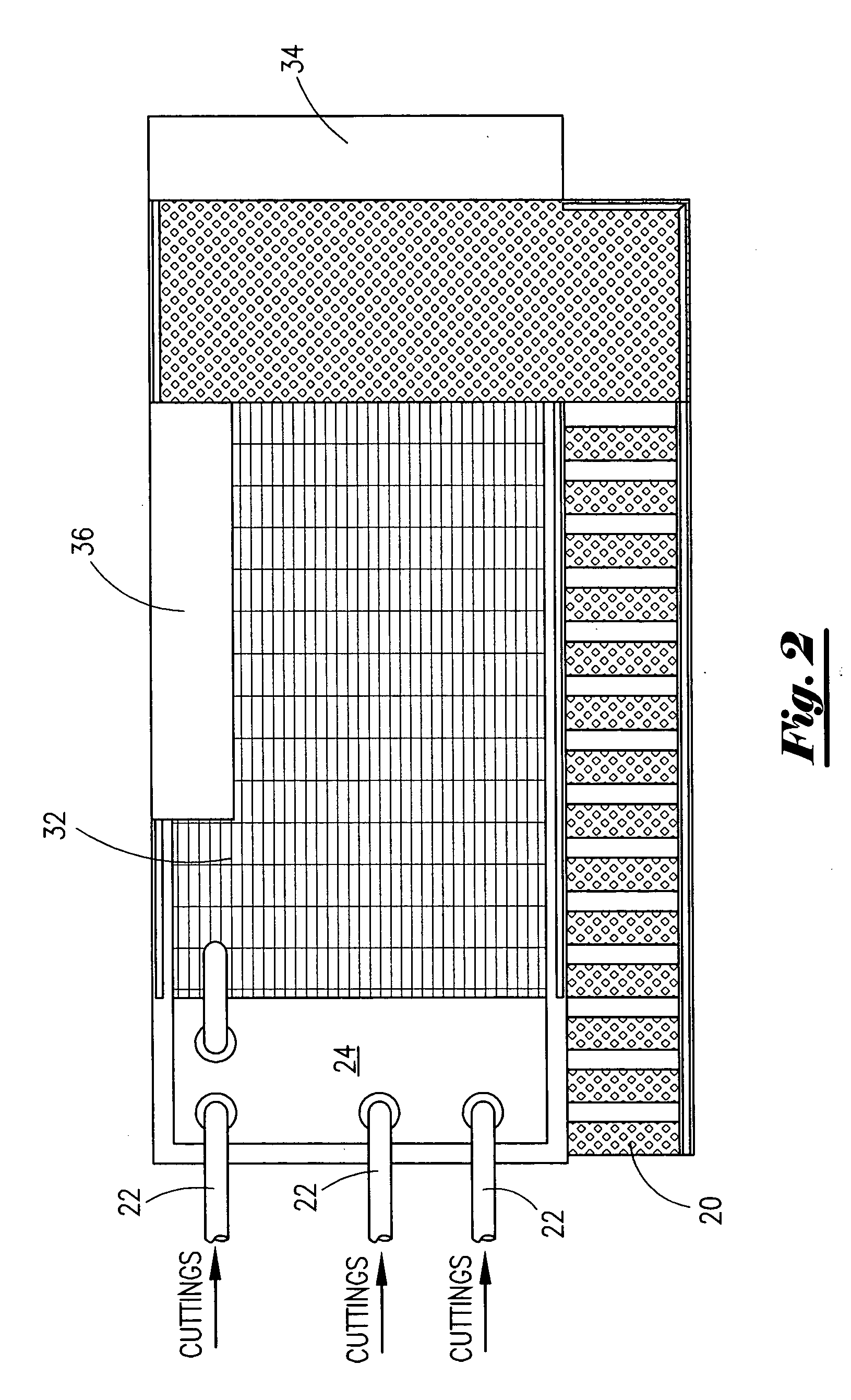
[0021] As shown in FIG. 1, the improved injection system 10 includes a open top receiving tank 12 that may be supplied on a skid 14 or provided by the drill site thus reducing the need for additional special equipment on site. In any which case the vacuum units and injections pump units 16 and 19 respectively may be mounted on separate or combined equipment skids as shown or independent of the tank unit 12. In any case a set of steps 20 or ladder for accessing the top of the open receiving tank is generally provided for workers to visually inspect and control the inflow of cuttings through tubing 22 to the receiving tank 12 from shaker screens or other cuttings processing systems via conventional conveying systems or the vacuum suction hood 24 and vacuum pumps 16 as shown. In this configuration vacuum is maintained on the cuttings hood 24 via suction line 23. Cuttings drop by gravity from the hopper 24 into the liquid filled receiving tank 12 where they are continuously agitated and...


PUM


Abstract

An improved cuttings system located adjacent a drilling rig's shale shaker system utilizing a vacuum collection/gravity fed processing system, thereby eliminating expensive and complicated cuttings transfer systems. The use of a vacuum cuttings collection system combined within a common fluid-filled open tank and submersible grinding pumps eliminate the need for extensive circulating and holding systems. Cuttings are sized and chemically prepared within the same tank and fed directly to an injection pump for discharge to cuttings transport tanks or injected down hole. Other improvements include non-restrictive cuttings sizing, filtering, and an injection pump cuttings relief system.

Description

1. FIELD OF THE INVENTION [0001] This invention relates generally to an improved processing system for preparing drill cuttings for injection into a well formation while drilling and more particularly to an improved process for sizing and processing the drill cuttings into a particulate matter for injection into cavities within the formation surrounding a well bore while drilling. 2. GENERAL BACKGROUND [0002] When drilling for oil and gas, or other types of wells, a hole is bored into the earth, typically by a drill bit. Drilling mud containing various cuttings fluids are circulated in and out of the well, lubricating the drill bit and carrying away the rock shale, sand, and earth being removed from the bore. The material being removed from the bore is called drill cuttings. While the drilling fluid is necessary to the drilling operation, the shear nature of its formulation makes the mud a contaminant to the environment. Once the contaminated drill cuttings and drill fluid are circu...

Claims


Application Information

Patent Timeline
IPC IPC(8): E21B21/06
CPCE21B21/066
Inventor REDDOCH, JEFFREY A. SR.
Owner REDDOCH SR JEFFREY A
Why Eureka
Try Eureka