Leaf seal, in particular for a gas turbine, and method of producing it

a gas turbine and seal technology, applied in the direction of engine seals, leakage prevention, machines/engines, etc., can solve the problems of limiting affecting the service life of the seal, and the axial pressure difference that the seal can withstand remains fairly low, so as to achieve the effect of precisely adjusting the distance between the leaves

Inactive Publication Date: 2007-05-31
ANSALDO ENERGIA IP UK LTD
View PDF3 Cites 21 Cited by
  • Summary
  • Abstract
  • Description
  • Claims
  • Application Information

AI Technical Summary

Benefits of technology

[0024] In this case, the distance between the leaves can be set especially accurately if the brazing foils used as spacers are ...

Problems solved by technology

However, they offer the advantage of low rotational friction and of a therefore virtually unlimited service life.
On the other hand, brush seals have higher friction losses on account of the friction between the bristle ends and the rotor shaft.
This results in wear, which limits the service life of the seal.
Firstly, the axial pressure difference that ...

Method used


Image

  • Leaf seal, in particular for a gas turbine, and method of producing it
  • Leaf seal, in particular for a gas turbine, and method of producing it
  • Leaf seal, in particular for a gas turbine, and method of producing it

Examples


Embodiment Construction

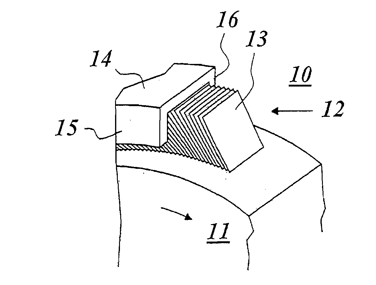
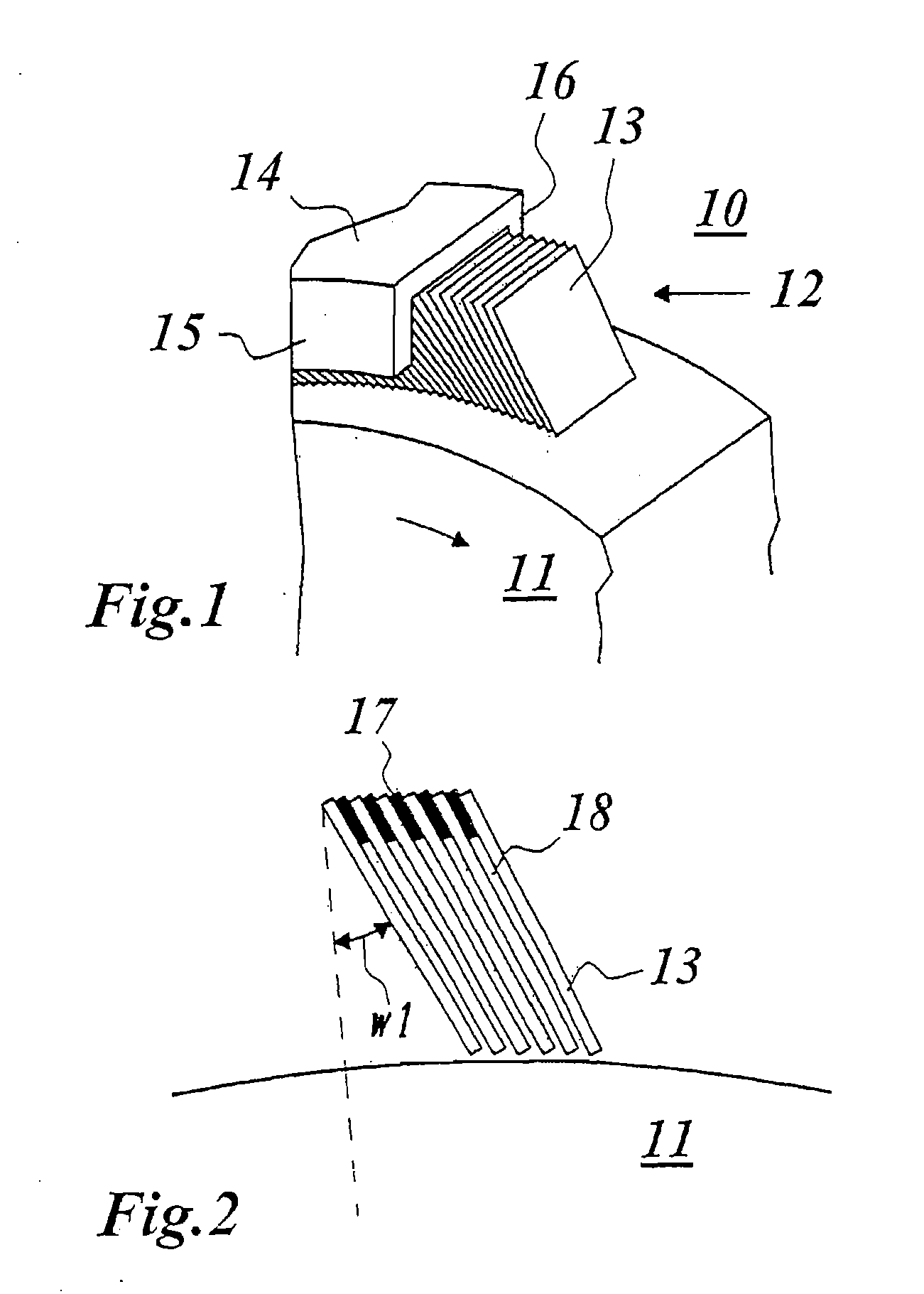
[0034] Shown in FIG. 1 in a perspective side view is a typical construction of a leaf seal as used in a gas turbine. The leaf seal 12 seals a rotor shaft 11, rotating in the arrow direction, of the gas turbine 10 with respect to a housing 14. A stack of tightly spaced-apart thin leaves 13 is arranged in a ring in the circular ring-shaped intermediate space between the rotor shaft 11 and the housing 14. With their surface, the leaves 13 are oriented parallel to the axis of rotation of the machine. According to FIG. 2, the leaves are tilted from the radial direction by an angle w1 and have a narrow gap or intermediate space 18 between them, which is preferably established by spacers 17 arranged between the leaves 13. FIG. 7 and FIG. 8 each show the situation in which the spacers have been produced from brazing foil 22 and placed between the leaves 13.

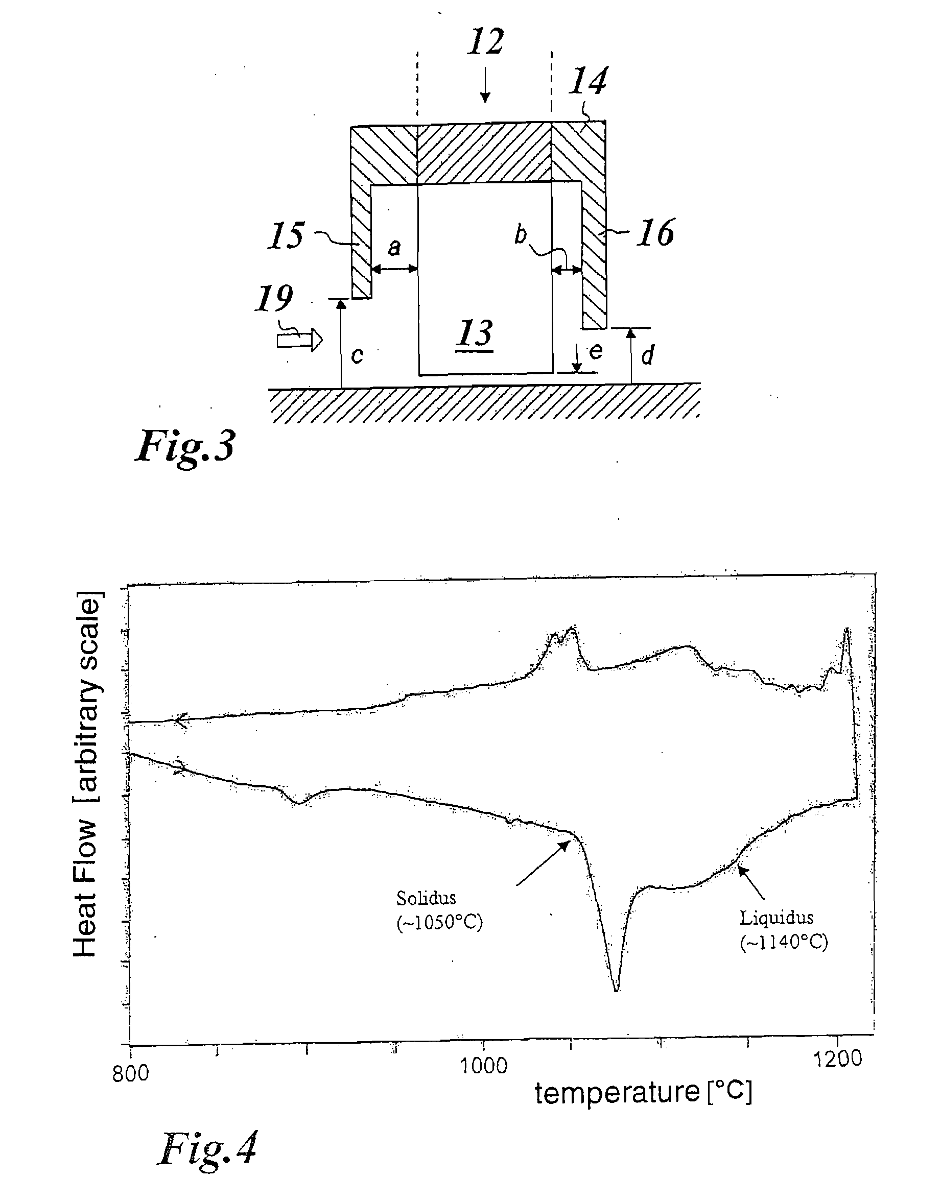
[0035] According to FIGS. 1 and 3, the air flow through the leaves 13 can be varied by using a front and a rear end plate 15 and 16, re...


PUM


Abstract

A leaf seal for sealing a shaft rotating about an axis, in particular in a gas turbine, includes a plurality of spaced-apart leaves arranged in a concentric circle around the axis and fixed in position by brazing, the leaves having surfaces oriented essentially parallel to the axis. The leaves are brazed to one another via intermediate spacers made of a brazing foil, so that a brazed joint is produced by brazing alloy from the brazing foils. The brazing temperature may be set to an optimum value just above the solidus temperature of the brazing foil, at which partial melting of the brazing foil occurs and penetration of liquid brazing alloy into the gap between the leaves is avoided.

Description

[0001] Priority is claimed to German Patent Application No. DE 10 2004 016 173.9, filed on Mar. 30, 2004, the entire disclosure of which is incorporated by reference herein. [0002] The present invention relates to the field of sealing in rotating machines. It relates to a leaf seal for sealing a shaft about an axis, in particular in a gas turbine, and to a method of producing such a leaf seal. BACKGROUND [0003] A gas turbine includes a rotor, on which various stages with compressor blades and turbine blades are provided, and of a stator housing. The rotor is mounted in bearings at each end of the rotor shaft. [0004] The control of the gas flow inside the gas turbine is of paramount importance with regard to both the functionality and the effectiveness. Sealing techniques are used at various locations along the rotor shaft in order to reduce the axial gas flow along the shaft. This is especially important next to the bearings in order to prevent the oil which is used in the bearings ...

Claims


Application Information

Patent Timeline
IPC IPC(8): F16J15/44F16J15/32
CPCF16J15/3292
Inventor RHODES, NIGEL ANTHONYHOEBEL, MATTHIASBREHM, WALTERSCHNELL, ALEXANDER
Owner ANSALDO ENERGIA IP UK LTD
Why Eureka
Try Eureka