Minimal bias switching for fiber optic gyroscopes

a fiber optic gyroscope and fiber optic gyroscope technology, applied in the field of fiber optic gyroscopes, can solve the problems of phase shift between waves, the phase shift needed to null the intensity difference can increase beyond the output range of optical modulators, and the low frequency content of feedback modulation can be reduced. , the effect of reducing the sensitivity to errors

Active Publication Date: 2007-05-31
HONEYWELL INT INC
View PDF3 Cites 20 Cited by
  • Summary
  • Abstract
  • Description
  • Claims
  • Application Information

AI Technical Summary

Benefits of technology

[0015] The result of predicting the integrated bias voltage and selectively performing 2π resets is that the 2π resets are performed at a higher frequency selected to drive the integrated bias voltage closer to zero. By reducing the low frequency content of the feedback modulation, the system and method reduces the sensitivity to errors associated with phase modulators that have a different response at low and high frequencies.

Problems solved by technology

Furthermore, they can be highly sensitive to very low rotation rates that can be a problem in other kinds of optical gyroscopes.
The resulting path length difference results in a phase shift between the waves propagating in opposite directions.
Specifically, waves propagating in opposite directions interfere when recombined and impinge upon photodetector, which measure the intensity of the combined wave.
One issue in closed loop fiber optic gyroscopes is that the phase shift needed to null the intensity difference can increase beyond the output range of the optical modulator.
However, the amount of modulation that can be provided is limited by the circuitry and the range of the optical modulator.
Unfortunately, in real modulators, Vπ can often depend upon many environmental factors such as temperature, radiation, and humidity.
If the reset overshoots or undershoots 2π, then a rate error is generated.
A problem not addressed by Vπ measurement systems is that Vπ can also depend upon the frequency of the applied voltage.
This decay corresponds to degraded low frequency performance of the modulator.
Since rotation is based on the feedback voltage needed to null the induced phase shift, the frequency dependence of Vπ introduces a rate error that can be significant for some applications.

Method used


Image

  • Minimal bias switching for fiber optic gyroscopes
  • Minimal bias switching for fiber optic gyroscopes
  • Minimal bias switching for fiber optic gyroscopes

Examples


Embodiment Construction

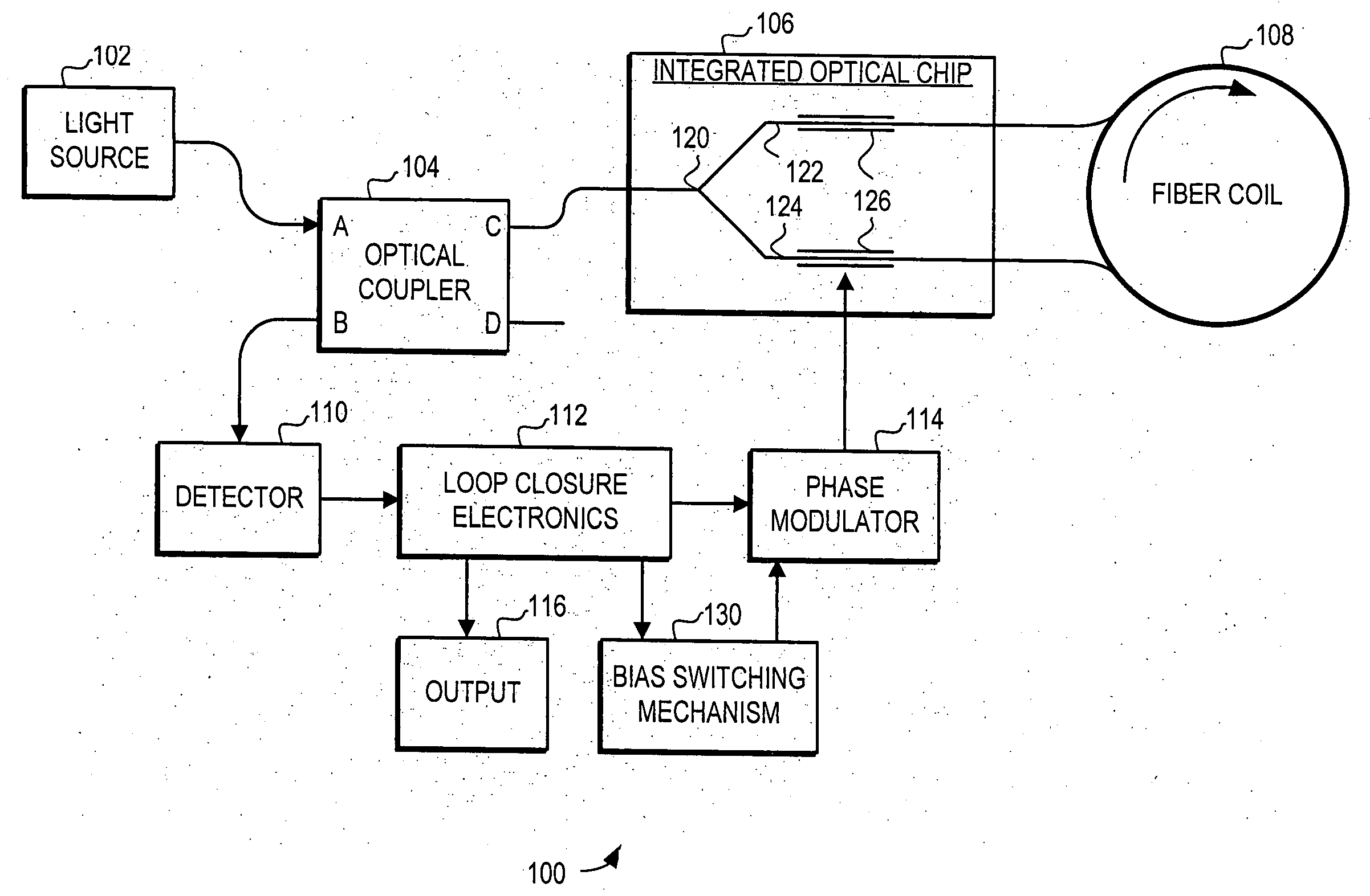
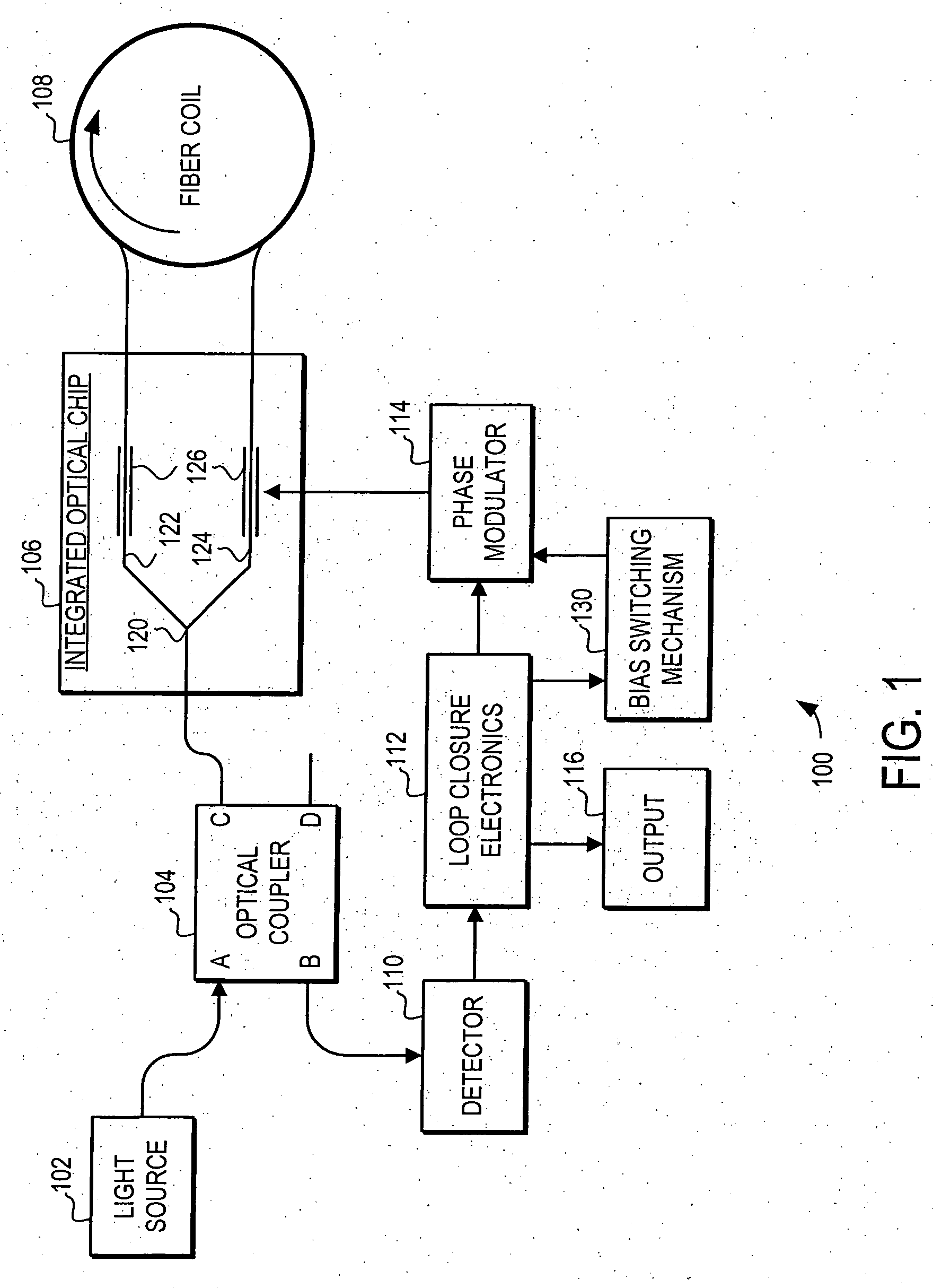
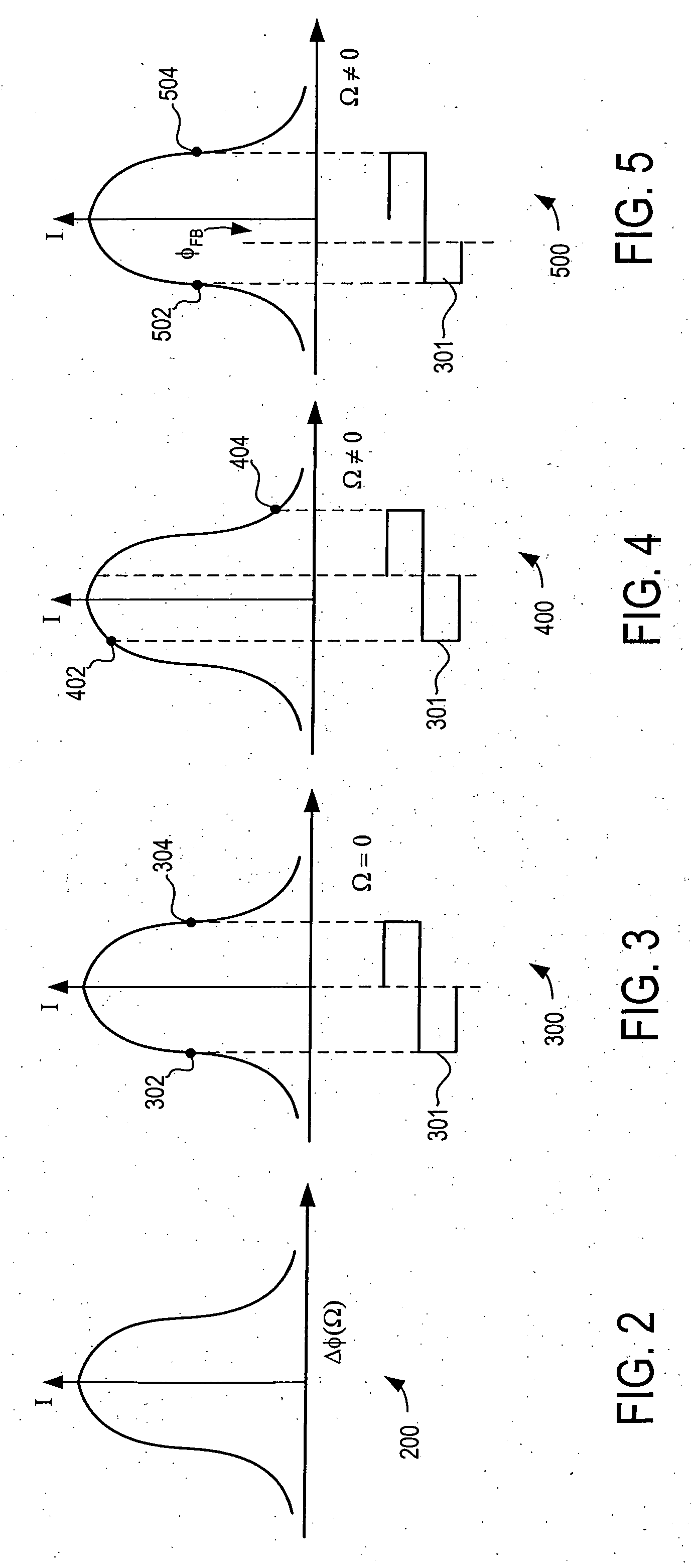
[0023] The embodiments of the invention provide a system and method for reducing the sensitivity of the rotation rate measurement to the frequency dependence of the feedback modulator. Specifically, the system and method uses a minimal bias switching technique to reduce rate errors associated with the low frequency 2π resets in a closed loop fiber optic gyroscope with a phase modulator with a different phase shift associated to low and high frequencies. In general, the minimal bias switching technique reduces the low frequency components of the feedback modulation drive by increasing the frequency of the 2π resets. As a consequence, the system and method reduces the low frequency component of the feedback modulator drive to avoid errors that occur with the low frequency 2π resets.

[0024] In operation, the minimal bias switching technique performs a 2π reset if such a reset is predicted to reduce the integrated voltage of the modulator drive, referred to as the modulator bias. Specif...


PUM


Abstract

A system and method is provided for reducing the sensitivity of the rotation rate measurement to the frequency dependence of the feedback modulator. Specifically, the system and method uses a minimal bias switching technique to reduce rate errors associated with the low frequency 2π resets in a closed loop fiber optic gyroscope with a phase modulator with a different phase shift associated to low and high frequencies. In general, the minimal bias switching technique reduces the low frequency components of the feedback modulation drive by increasing the frequency of the 2π resets. As a consequence, the system and method reduces the low frequency component of the feedback modulator drive to avoid errors that occur with the low frequency 2π resets.

Description

STATEMENT REGARDING FEDERALLY SPONSORED RESEARCH OR DEVELOPMENT [0001] This invention was made with Government support under contract 009Z9004 awarded from the Boeing Corporation. The Government has certain rights in this invention.FIELD OF THE INVENTION [0002] This invention generally relates to fiber optic gyroscopes, and more specifically relates to feedback modulation in closed-loop fiber optic gyroscopes. BACKGROUND OF THE INVENTION [0003] Fiber optic gyroscopes are used to accurately sense rotation of an object supporting such a gyroscope. Fiber optic gyroscopes can be made quite small and can be constructed to withstand considerable mechanical shock, temperature change, and other environmental extremes. Due to the absence of moving parts, they can be nearly maintenance free. Furthermore, they can be highly sensitive to very low rotation rates that can be a problem in other kinds of optical gyroscopes. [0004] A typical fiber optic gyroscope includes a coiled optical fiber woun...

Claims


Application Information

Patent Timeline
Patent Type & Authority Applications(United States)
IPC IPC(8): G01C19/72
CPCG01C19/726
Inventor GREENING, THOMAS C.KHATRI, SVEN H.NEWLIN, MATTHEW P.
Owner HONEYWELL INT INC
Why Eureka
Try Eureka