LED lighting system for use in environments with high magnetics fields or that require low EMI emissions

Active Publication Date: 2007-05-31
EVERBRITE
View PDF10 Cites 104 Cited by
  • Summary
  • Abstract
  • Description
  • Claims
  • Application Information

AI Technical Summary

Benefits of technology

[0022] The end result is that the radiation issues associated with florescent, incandescent, or metal halide lighting systems have been eliminated, without the thermal, glare, and hot spot i

Problems solved by technology

Current limiting series resistors create additional heat, waste el

Method used


Image

  • LED lighting system for use in environments with high magnetics fields or that require low EMI emissions
  • LED lighting system for use in environments with high magnetics fields or that require low EMI emissions
  • LED lighting system for use in environments with high magnetics fields or that require low EMI emissions

Examples


Embodiment Construction

Lighting System

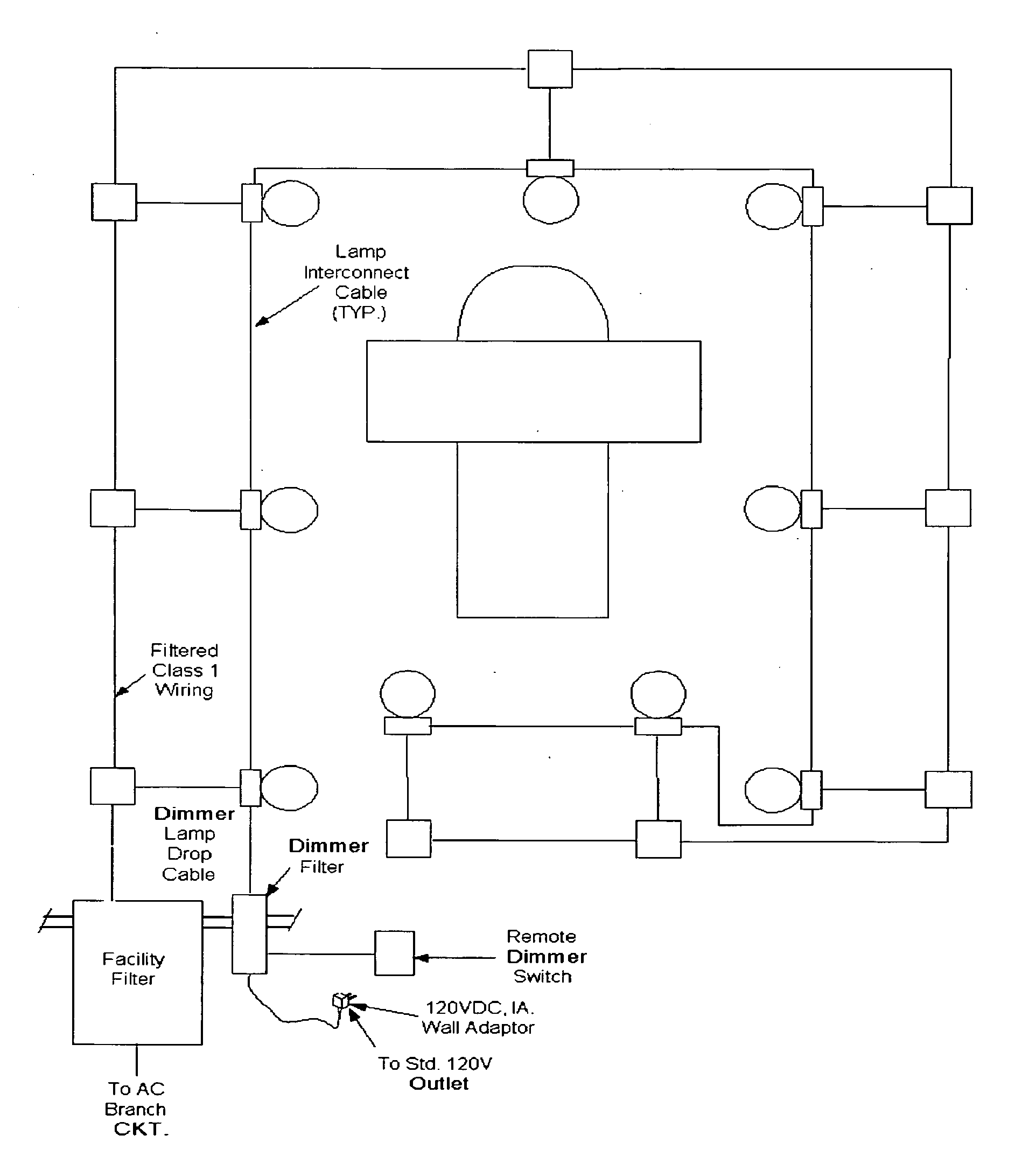
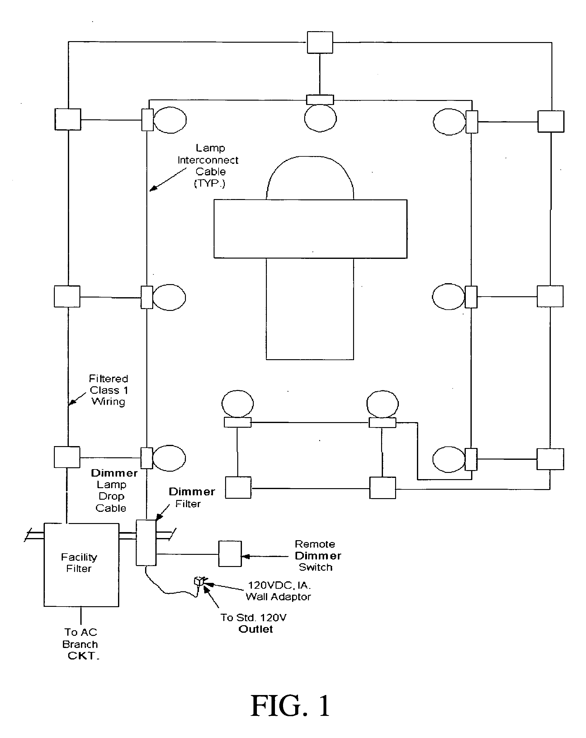
[0030]FIG. 1 is a block diagram of a typical MRI room. The MRI magnet imaging equipment and patient table are centrally located in the room, which is enclosed by an electromagnetic shield, including all doors, windows, vents, and any other penetrations into the room.

[0031] The LED lighting fixtures LF1 through LF9 are powered by ordinary mains AC supplied via junction boxes and conduit as specified by applicable electrical codes. Power for the lighting circuit is supplied to the room through an EMI facility filter installed on the outside of the room shield on a penetration panel. This ensures that any EMI signals on the power line are removed or reduced to an acceptable level before entering the room.

[0032] The LED lighting fixtures are optionally connected to a dimmer control circuit via low-voltage Class 2 Lamp Interconnect Cables in a “daisy-chain” fashion. The dimmer control circuit also passes through a filter on the penetration panel to remove any EMI from ...


PUM

PropertyMeasurementUnit
Poweraaaaaaaaaa
Magnetic fieldaaaaaaaaaa
Flexibilityaaaaaaaaaa

Abstract

This invention is a non-ferrous lighting fixture and non-ferrous lighting system that can be used in areas with high magnetic fields or that require low EMI emissions, such as MRI operating rooms. This invention uses LED's to provide a high-intensity, quality white or other color light that is softened by reflectors and diffusers, and can be dimmed to provide flexible lighting levels. The flexible lighting levels can range from the maximum light used for patient procedures and equipment servicing/maintenance to the lowest light level used to keep a patient comfortable while facing upward on the MRI scanning table. Moreover, by using an aluminum substrate printed circuit board, this invention resolves the thermal issues associated with high-intensity lighting. Not only does this invention resolve glare and hot spot issues, it protects the user and installer from electrical hazards associated with potentially high voltages, as well. Finally, because this invention is completely non-ferrous, it does not interfere with the integrity of the MRI equipment's readings.

Description

CROSS REFERENCE TO RELATED APPLICATION [0001] These inventors claim priority from U.S. Provisional patent application # 60 / 739,638 filed Nov. 26, 2005 with attorney docket # of EB 01.FIELD OF THE INVENTION [0002] This invention relates to lighting systems, specifically it is a light emitting diode (LED) lighting system that is designed entirely of non-ferrous materials and employs low RF noise driver electronics for use with high magnetic field / low electromagnetic interference (EMI) environments, such as magnetic resonance imagery (MRI) equipment applications. DISCUSSION OF RELATIVE ART [0003] MRI technology utilizes extremely strong magnetic fields in the order of 0.5 to over 7 Tesla. In addition, the nature of MRI signal acquisition requires a very low radio frequency (RF) noise environment to preserve image quality. These strong magnetic fields and low noise requirements pose substantial difficulties for equipment operating in the vicinity of a MRI scanner. In the past, when ligh...

Claims


Application Information

Patent Timeline
IPC IPC(8): F21V29/00
CPCA61B2019/521F21V3/04F21V7/22F21V15/01F21V29/004F21V29/89G01R33/28H05B33/0803H05B33/0815H05B33/0887Y02B20/341F21Y2101/02A61B2090/309F21Y2105/10F21Y2115/10F21V7/24F21V7/28H05B45/56H05B45/36H05B45/345H05B45/355F21V29/505Y02B20/30
Inventor MONDLOCH, MICHAEL J.PYNE, HARRY M.VENHAUS, DAVID A.
Owner EVERBRITE
Why Eureka
Try Eureka