Incorporation of particulate additives into metal working surfaces

Inactive Publication Date: 2007-05-31
FRICSO
View PDF9 Cites 14 Cited by
  • Summary
  • Abstract
  • Description
  • Claims
  • Application Information

AI Technical Summary

Benefits of technology

[0016] The present invention is a method and device for incorporating particulate additives into

Problems solved by technology
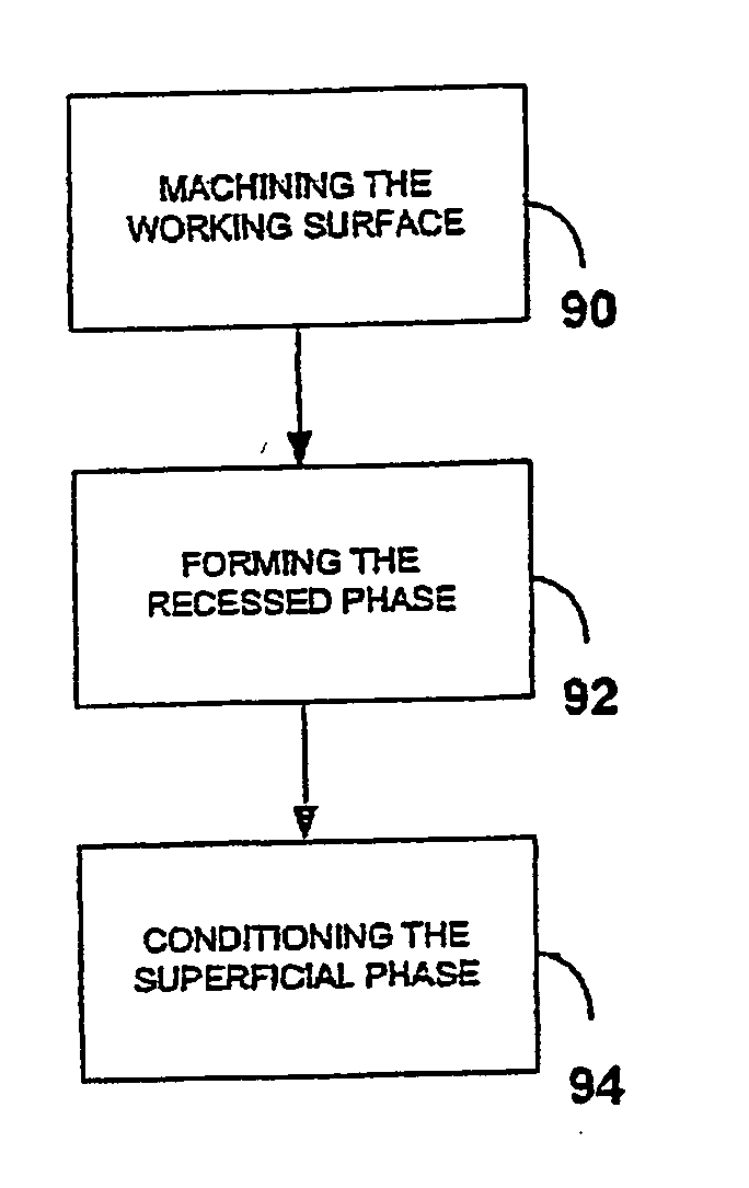
In this condition, often referred to as boundary lubrication, the lubricant is ineffective and the friction and wear are high.
Furthermore, the harder the abrasive grain, the more material it will remove per unit volume

Method used


Image

  • Incorporation of particulate additives into metal working surfaces
  • Incorporation of particulate additives into metal working surfaces
  • Incorporation of particulate additives into metal working surfaces

Examples


example 1

[0181] The experimental set-up is described schematically in FIG. 18, to which reference is now made. An interchangeable set of carbon steel discs of 30 mm diameter, such as disc 186, rotatable around an axle, is made to rotate against a flat counter-plate 192 for measuring wear. The discs are made of carbon steel grade 1045, having an HRC of 27-30. Electrical motor or gear 190 supplies the torque for the rotation. Counter-plate 192 is made of a copper alloy (UNS C93700 (HRC=22-24)), ground to an average roughness (Ra) of 0.4 micrometers. Counter-plate 192 has a support 194, which has an adjustable height for controlling the force applied on disc 186.

[0182] The control discs have a conventional grinding finish (Ra=0.4 micrometers), whereas the test discs undergo further treatment by micro-grooving face 196 of the disc, and then by lapping, in accordance with the present invention. During the experiments, a permanent load of a 100 N is applied to the disc in the direction of the cou...

example 2

[0187] A roller on block tribo-tester was used to evaluate the tribological properties of rollers processed according to the present invention, in a “one drop test”. The test rig is described-schematically in FIG. 19. A rotating roller 2 is brought into contact with a stationary block 3 under a given load P while a very small amount of lubricant (one drop) is applied to the contact. A force transducer 4 is used to measure the friction force F and a proximity probe 9 measures the variation in the gap, thus providing the total wear of roller 2 and block 3. Both friction and wear are continuously monitored and recorded as functions of time. The test is stopped at the occurrence of any one of the following three events: (a) the friction coefficient=F / P reaches a value of 0.3; (b) seizure starts between the roller and the block (characterized by a sudden, sharp increase in friction and corresponding increase in noise level), or (c) the friction reaches a maximum value and starts decreasi...

example 3

[0192] A roller on block tribo-tester was used to evaluate the tribological properties of rollers in a “one drop test”. Sliding distance tests were performed on each of four hardened-steel roller specimens, using a hardened-steel block as the counter-surface.

[0193] Roller specimen I was prepared using a conventional lapping method;

[0194] roller specimen II was prepared using a lapping method of the present invention;

[0195] roller specimen III was prepared by grooving followed by the conventional lapping method used in preparing roller specimen I, and

[0196] roller specimen IV was prepared by grooving followed by the inventive lapping method used in preparing roller specimen II.

[0197] The results of the sliding tests are presented in Table 4. Roller specimen II, prepared using a lapping method of the present invention, achieved a sliding distance of 1373 meters, nearly double that of reference roller specimen I, which was prepared using a conventional lapping method. Surprisingly...


PUM

PropertyMeasurementUnit
Fractionaaaaaaaaaa
Fractionaaaaaaaaaa
Fractionaaaaaaaaaa

Abstract

A mechanical device for lapping, and a method therefor, the device including: (a) a metal workpiece having a metal working surface; (b) a contact surface, disposed generally opposite the working surface, for moving in a relative motion to the working surface; (c) abrasive particles disposed between the contact surface and the working surface, and (d) a mechanism, associated with the working surface and/or the contact surface, for applying the relative motion, and for exerting a load in a substantially normal direction to the contact surface and the working surface, the contact surface for providing an at least partially elastic interaction with the plurality of abrasive particles, wherein, associated with the contact surface is a particulate additive, and wherein, upon activation of the mechanism, the relative motion under the load causes a portion of the abrasive particles to penetrate the working surface, and wherein the relative motion under the load effects incorporation of a portion of the particulate additive into the metal working surface.

Description

FIELD AND BACKGROUND OF THE INVENTION [0001] The present invention relates to metal working surfaces having particulate additives such as solid lubricants, and, more particularly, to a method and device for incorporating such particulate additives into metal working surfaces. [0002] In order to reduce friction and wear in mechanically interacting surfaces, a lubricant is introduced to the zone of interaction. As depicted schematically in FIG. 1A, under ideal lubricating conditions, the lubricant film 20 between opposing surfaces 32 and 34, moving at a relative velocity V, forms an intact layer which permits the moving surfaces to interact with the lubricant. Under such conditions, no contact between surfaces 32 and 34 occurs at all, and the lubricant layer is said to carry a load P that exists between the opposing surfaces. If the supply of lubricant is insufficient, a reduction in the effectivity of the lubrication ensues, which allows surface-to-surface interactions to occur. [000...

Claims


Application Information

Patent Timeline
IPC IPC(8): B24B51/00B24B1/00B24B37/00
CPCB24B37/00Y10T29/49702Y10T29/49707
Inventor SHTEINVAS, BELAMELAMED, SEMYONMANDEL, KOSTIA
Owner FRICSO
Why Eureka
Try Eureka