Flash memory architecture with separate storage of overhead and user data

a flash memory and overhead technology, applied in the field of flash memory systems, can solve the problems of consuming a significant amount of power, reducing the susceptibility of hard disk drives and floppy disk drives to failure, and reducing so as to reduce the amount of memory consumed by dedicated overhead functions, the effect of efficient use of overhead memory

Inactive Publication Date: 2007-05-31
MICRON TECH INC
View PDF2 Cites 39 Cited by
  • Summary
  • Abstract
  • Description
  • Claims
  • Application Information

AI Technical Summary

Benefits of technology

[0034] The present invention discloses a flash memory system designed to reduce inefficiencies and liabilities inherent in systems where user data and overhead data such as Error Correction Data are stored in the same sector. The present invention further discloses a method and apparatus for use in a non-volatile storage medium that segregates overhead data from user data, while maintaining a cross reference between the overhead data and user data. The present invention further discloses a method and apparatus for minimizing the amount of memory consumed by dedicated overhead functions. The present invention further discloses a method and apparatus for segregating user data from overhead data in a way that makes efficient use of overhead memory when one Logical Block Addresses repeated more often than other Logical Block Addresses. The present invention further discloses a method and apparatus for segregating overhead data from user data in a way that makes efficient use of overhead memory in when available Logical Block Addresses are used at an equal or substantially equal rate. The present invention further discloses a method and apparatus for segregating user data from overhead data in a way that makes efficient use of overhead memory when the comparative rate of usage of various Logical Block Addresses is variable or unknown.

Problems solved by technology

Hard disk drives and floppy disk drives suffer several deficiencies which are not shared by flash memory technology.
These components give rise to reliability problems and magnify the hard disk drive's and floppy disk drive's susceptibility to failure resulting from the vibration and shock of being dropped or bumped.
Secondly, a motor driven disk drive consumes a significant amount of power, substantially shortening the operational time between battery chargings.
Finally, accessing data stored in the hard disk drive or the floppy disk is a relatively slow process.
In addition, the rugged design of the typical flash memory system withstands environmental conditions and physical mishandling that would otherwise be catastrophic to the hard disk drive or the floppy disk drive.
Finally, the power consumption of the typical flash memory system is considerably lower than the hard disk drive's and the floppy disk drive's power consumption.
One of the disadvantages commonly found in Flash Memory devices and systems is their inability to replicate data addressing, storage and retrieval procedures implemented by the hard disk drive and the floppy disk drive.
Another limitation of flash memory technology is the inability to perform a write operation to a sector of a flash memory cell currently storing data.
Voltage levels required to erase a sector of a flash memory cell typically degrade the insulative layer protecting the floating gate.
As a result of cumulative erase operations, the insulation will eventually fail, dislodging bound electrons on the floating gate.
Sophisticated erasure programs can ameliorate the degradation experienced by the erase operation, but have not yet eliminated deleterious effect altogether.
Moreover, the loading and running of sophisticated erasure programs is time consuming, adding to the delay that the erase operation itself creates.
Failure to employ protective erase programs only accelerates the degradation resulting from erasure, substantially shortening the useful life of a flash memory cell.
Therefore, while the data storage procedure implemented by the typical flash memory system represents an improvement over hard and floppy disk storage in terms of moving parts and power consumption, it suffers potential liabilities which must be overcome.
Because the 
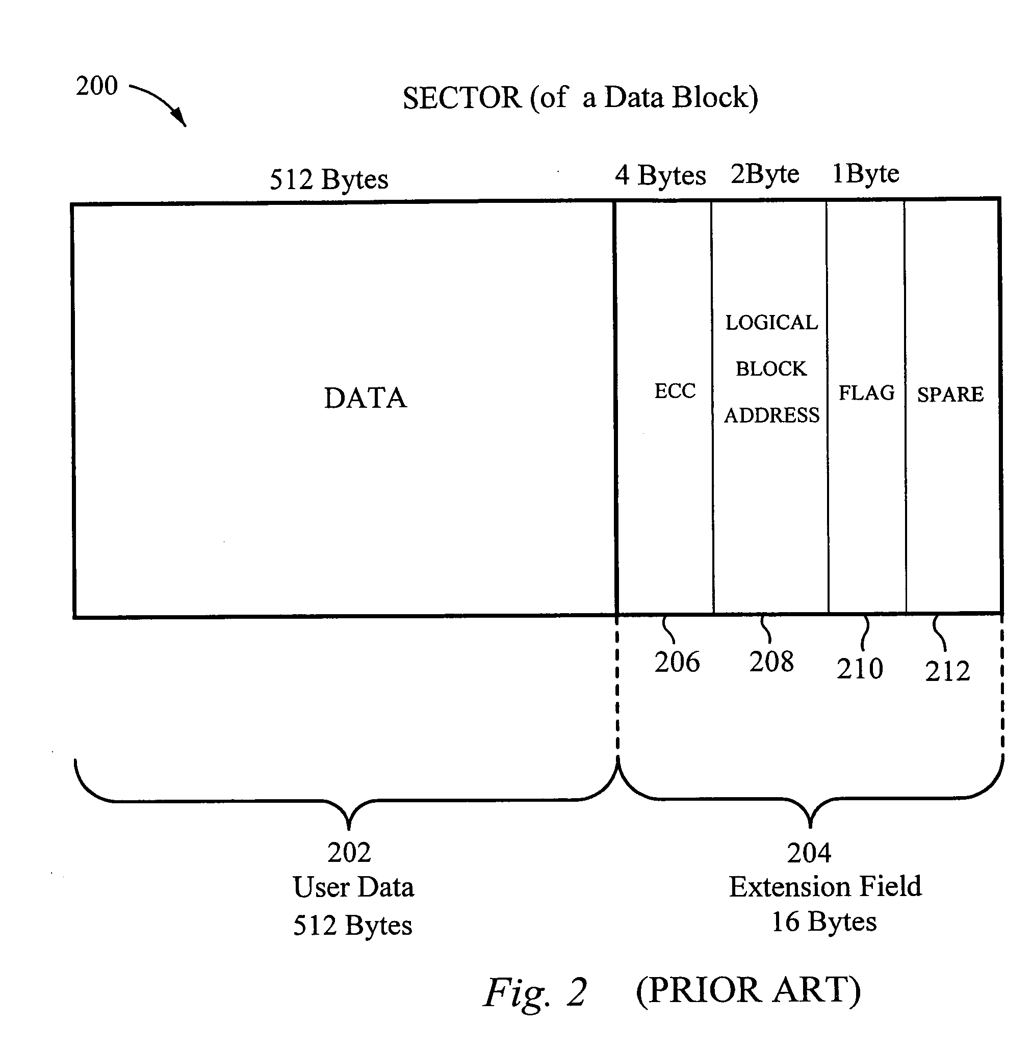
Data Field and the Extension Field are part of the same sector according to the prior art, a significant limitation of the prior art has been the inability to erase User Data and Overhead Data independently.
Architectural limitations prohibit targeted erasures below the sector level.
It is recalled however that repeated writing and erasing degrades the life of a flash memory, and that wear-leveling programs are typically employed to ensure a substantially even utilization of all physical data storage areas within a flash memory.
It will be recalled that a management algorithm typically attempts to cycle through all Physical Data Blocks before returning to the original Physical Data Block, thereby producing an even rate of use or wear among Physical Data Blocks.
This is primarily because space managers consume valuable memory, and correlation to a finer level of memory would consume more memory.
Although correlation between logical and physical memory must be maintained, RAM space managers 400 consume valuable memory.
Due to the volatile nature of the space manager 400, loss of power erases the data stored in a volatile RAM such as that used in the typical Space Manager.
The silicon area necessary for a large addressable storage capacity, however, typically makes it economically unfeasible to form both the controller and the actual flash memory device on the same integrated circuit.
Although the space manager 400 enables the typical flash memory system to achieve superior performance, this superior performance is attained at a significant cost in silicon area on the integrated circuit on which the controller is formed.
This process is both time consuming and complex.
A second problem stemming from the mixing of User Data and Overhead Data in the same sector deals with gate degradation.
As earlier noted, repeated write and erase cycles eventually “wear-out” a flash memory system.
Relying on degraded error correction field to monitor and possibly correct User Data is problematic at best.
Finally, when overhead data and user data are stored in the same sector, it was not possible to independently program or erase the overhead data were user data.

Method used


Image

  • Flash memory architecture with separate storage of overhead and user data
  • Flash memory architecture with separate storage of overhead and user data
  • Flash memory architecture with separate storage of overhead and user data

Examples


Embodiment Construction

[0068] The embodiments recited herein are neither intended to limit the scope of the invention, nor to exhaust every possible variation or nuance of the described invention. Minor variations of the disclosed invention will immediately become apparent to those skilled in the art. In particular, numerous illustrations are made with respect to data storage architecture, and the fields and registers within a Flash Memory Unit. The descriptive terms such as Dedicated Overhead Blocks, Overhead Pages, Overhead Segments, Super Overhead Fields and other architectural components are arbitrary term used to illustrate the architecture, data storage fields and registers of the present invention. Equivalent structures or architectures may be designed using any variety of architectural terms. Similarly, the relative storage capacities of various data storage fields are not intended to limit the present invention to the particular embodiment illustrated. Neither are the number of component memory f...


PUM


Abstract

A flash memory system segregates overhead data from user data so that overhead data may be address, programmed and erased independently from user data. The non-volatile memory medium of a flash memory system is mapped into a plurality of separate and separately addressable memory blocks that are independently programmable and independently erasable, including Dedicated Overhead Blocks and Dedicated Data Blocks. The Dedicated Overhead Blocks are mapped according to a plurality of distinguishably addressable segments. User Data defined by a VLBA is stored in a Dedicated Data Block within the flash memory. Successively generated sets of Overhead Data, such as a cross reference to the physical address of the user data, flags, and Error Correction Data generated in conjunction with incoming User Data, are stored in respective segments in the Dedicated Overhead Blocks. When a Dedicated Overhead Block is designated for erasure, any current overhead segments are consolidated and moved to a new Dedicated Overhead Block., and the full or obsolete block is erased.

Description

FIELD OF THE INVENTION [0001] The present invention relates to the field of flash memory systems. More particularly, the present invention relates to a mapping of a flash memory array that segregates data and overhead storage. BACKGROUND OF THE INVENTION [0002] Flash memory technology is an electrically rewritable nonvolatile digital memory medium. Being non-volatile, it does not require a sustained voltage to retain digital data within its memory. A flash memory cell typically stores charge on a floating gate to represent a first logic state in the binary state system, while the lack of stored charge represents a second logic state in the binary state system. Flash memory cells typically support a write operation, a read operation, and an erase operation. Like traditional rotating storage media, flash memory is non-volatile. Because of this, data stored in it is retained when power is cut off. This makes it particularly useful for a number of applications such as digital photograph...

Claims


Application Information

Patent Timeline
Patent Type & Authority Applications(United States)
IPC IPC(8): G06F12/00G11C16/02G06F3/06G06F12/02G11C16/10
CPCG06F3/0616G06F3/064G11C16/102G06F12/0246G06F3/0679G06F3/0605G06F3/0631G06F3/0647G06F12/1009G06F2212/1036G06F2212/214G06F2212/657G06F2212/7201G06F2212/7204G06F2212/7211
Inventor ESTAKHRI, PETRONEMAZIE, SIAMACK
Owner MICRON TECH INC
Why Eureka
Try Eureka