System and die for forming a continuous filament reinforced structural plastic profile by pultrusion/coextrusion

a technology of continuous filament and structural plastics, applied in the field of reinforced plastic composite materials, can solve the problems of pvc fence and rail materials, prone to corrosion attack, and thermoplastics that do not have the strength and rigidity of wood and lumber, etc., and achieve the effect of strengthening the thermoplastic structur

Inactive Publication Date: 2007-06-07
SAINT GOBAIN PERFORMANCE PLASTICS CORP
View PDF23 Cites 36 Cited by
  • Summary
  • Abstract
  • Description
  • Claims
  • Application Information

AI Technical Summary

Benefits of technology

[0010] A system for providing a reinforced thermoplastic structure is disclosed. The system may comprise a resin wetting element for applying a first thermoplastic resin to an external surface of a plurality of reinforcing filaments. A die may be provided having (i) a first portion comprising a filament alignment channel for receiving the reinforcing filaments, (ii) a second portion for receiving a second resin, contacting the second resin with the reinforcing filaments, and at least partially solidifying the first and second resins to form a reinforced thermoplastic structure having a predetermined outer shape; and (iii) a third portion for applying a third thermoplastic resin to an exterior surface of said reinforced thermoplastic structure. The filament alignment channel may be sized to allow forward movement the filaments and the first thermoplastic resin to pass into second portion of the die and to prevent reverse movement of the first thermoplastic resin and the second thermoplastic resin backwards through the filament channel. The second portion of the die may have an angled resin inlet for receiving the second resin at a resin input angle that is non-orthogonal to a longitudinal axis of the filament.
[0011] A multistage die is disclosed for forming a reinforced thermoplastic structure. The die may comprise a first stage comprising a plurality of filament receiving channels for receiving a plurality of reinforcing filaments pre-wetted with a first thermoplastic resin and directing the pre-wetted filaments into a second stage of the die along a process direction. The second stage may comprise a filament receiving portion and a resin inlet for receiving a second thermoplastic resin at melt state, said resin inlet having an inlet angle that is non-orthogonal to the process direction; the second stage further having a curved flow channel to effect a smooth change in direction of movement of the second thermoplastic resin from an inlet direction to the process direction. The die may comprise a third stage comprising a capping resin inlet for receiving a third thermoplastic resin at melt stage. The curved flow channel of the. second stage may cause the incoming second thermoplastic resin to contact the reinforcing filaments and the first resin to form a reinforced composite material.

Problems solved by technology

Thermoplastics typically do not have the strength and rigidity of wood and lumber and, therefore, the rail for the fence and railing needs a steel or aluminum reinforcement channel inside the rail.
Metal fence and rail materials, as well as the metal reinforcements used with current PVC fence and rail materials, are prone to corrosion attack, and lose strength in long-term endurance tests.
Additionally, where dark-colored thermoplastics materials are employed, thermal expansion problems can arise due to differences in expansion between opposing sides of the product when the product is exposed to sunlight.
Since the dark color absorbs heat more readily on the sun-facing side of the product, the resultant uneven heat buildup causes the rail to deform.
An additional problem is the lack of long-term stiffness of polymeric products, which has limited the rail span between the posts to lengths less than traditional lumber and metallic rails.
Conventional continuous filament reinforced thermoplastic profile products produced using conventional pultrusion processes still suffer from deficiencies in mechanical properties in the cross direction (e.g., flexural strength, tensile strength, impact strength, and compression strength), due typically to poor bonding between the substrate resin and the filaments.
This poor bonding is primarily due to poor resin wet-out of the filaments by the resin.
Additionally, cracking, splitting and separation of filaments in these profiles can easily occur during transportation, application, and installation.
Both of these approaches may result in a higher than desirable profile weight.
Additionally, conventional pultrusion processes for incorporating long filaments are relatively slow, and thus result in an undesirably low output rate (e.g., frequently on the order of only 2-3 feet per minute).
The slowness of the process is due to the time required for (1) melting of the thermoplastics, and (2) wet-out of the melted thermoplastics around the filaments.
Filament wet-out with thermoplastic resin is typically poor, even at higher temperature and longer residence times, due to the relatively high viscosity of thermoplastic materials.
Further, incompatibility between the thermoplastic resin and the filament material can also lead to poor wet-out.
The additional machines, however, take up additional manufacturing floor space and involve larger amounts of capital investment, thus leading to increased costs.
Alternatively, conventional filament reinforced thermoplastic profile products produced using conventional extrusion processes suffer from deficiencies in mechanical properties in the cross direction because current processes only allow for the incorporation of very short filament lengths.
Such processes can result in filament lengths of about one tenth of their originally added length.
If the filament length is too long (i.e., over ½-inch), the filaments will form a bridge at the introduction hopper, clogging the hopper and inhibiting feeding of the filaments into the extruder.
Such short filament lengths are undesirable for use as reinforcement for thermoplastic products because they do not provide the enhanced strength that is desired.
Additionally, filament loading using such processes is low.

Method used


Image

  • System and die for forming a continuous filament reinforced structural plastic profile by pultrusion/coextrusion
  • System and die for forming a continuous filament reinforced structural plastic profile by pultrusion/coextrusion
  • System and die for forming a continuous filament reinforced structural plastic profile by pultrusion/coextrusion

Examples


example

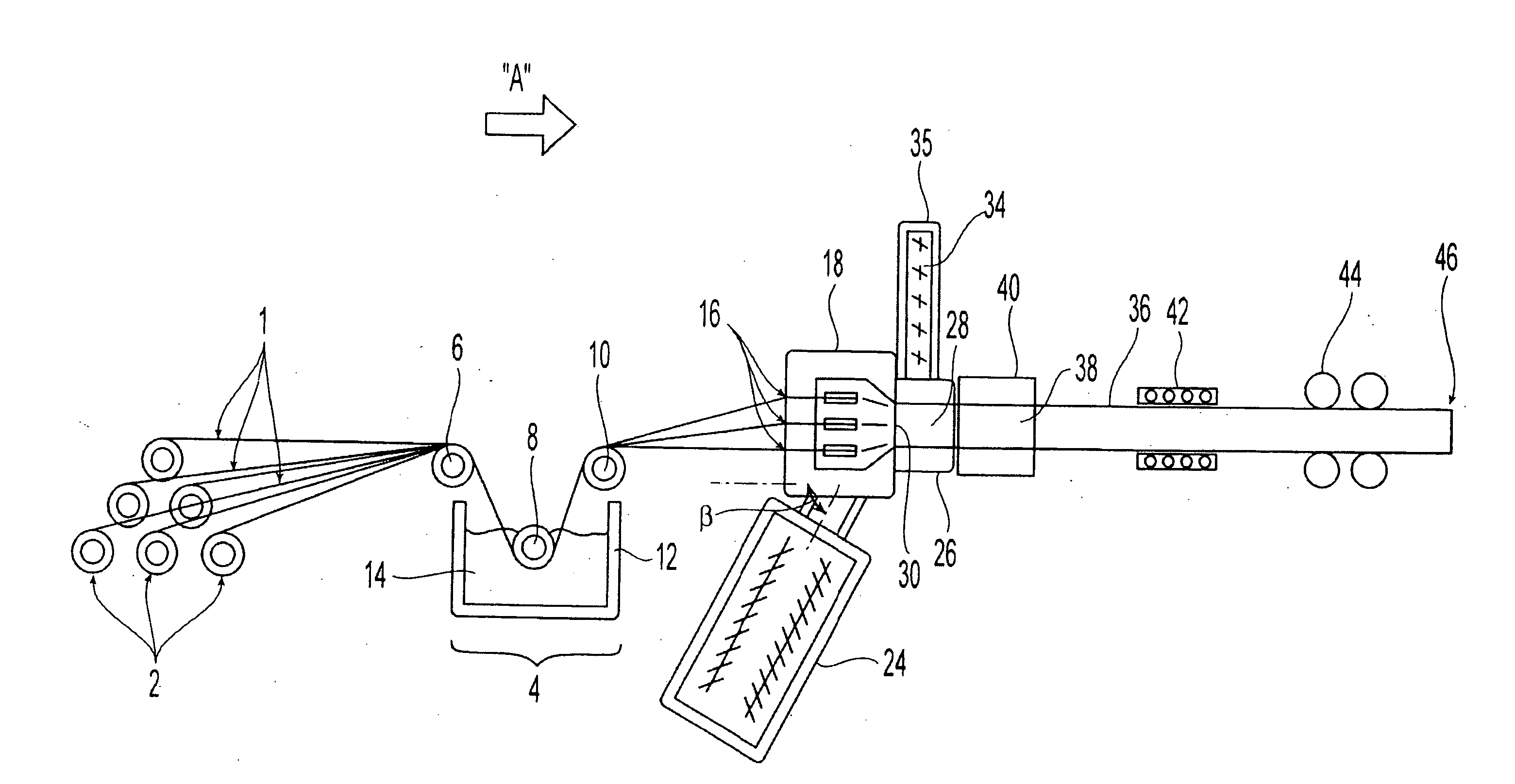
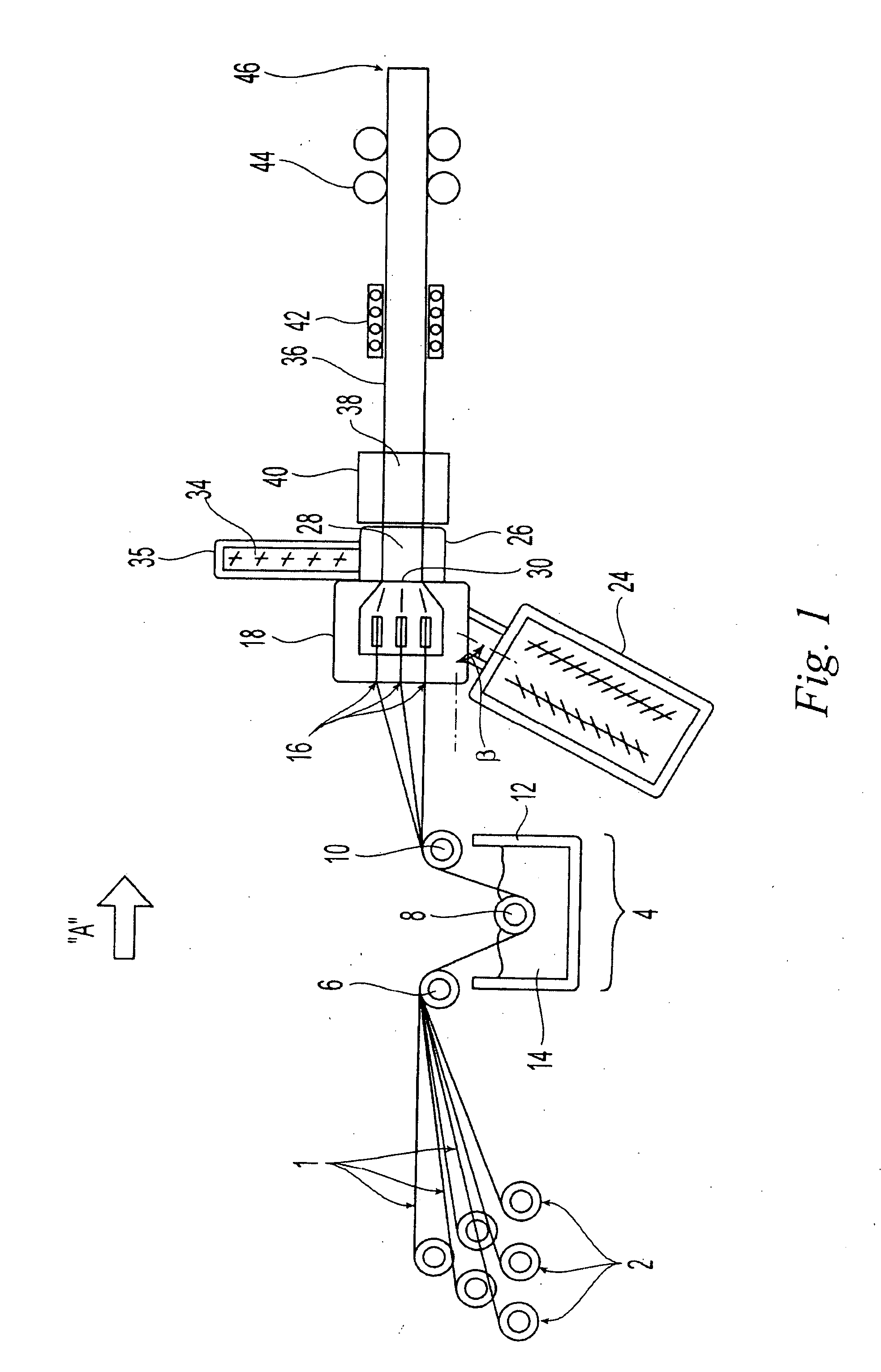
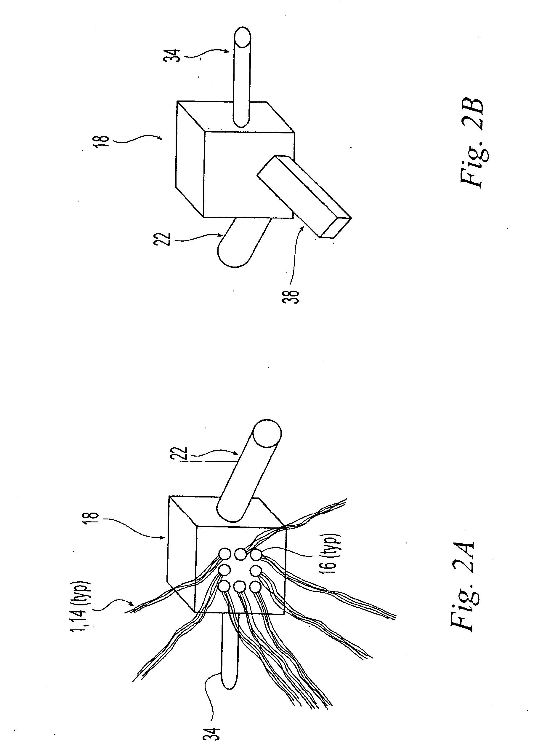
[0078] A PVC-Glass fiber / PVC Plastisol-Acrylic cap stock profile extrusion was carried out using a 3.5″ Davis Standard single screw extruder as a main extruder for PVC substrate extrusion, a three stage 0.705″×0.705″ crosshead die, with a square hole in the center, a 1.5″ Polytruder single screw extruder, a vacuum calibration system, a fiber creel, and a plastisol resin bath. The substrate resin (second resin 22) was a rigid PVC material having a composition as shown in the table below.

Parts byMaterialweightSource of materialOxyVinylsPolyvinyl100.00OxyVinyls, Dallas, TX216chlorideMark 1900Stabilizer1.50Chemtura Corporation,Middlebury, CTKronos 2073Titanium1.00Kronos, Inc., Cranbury, NJdioxideRheolub 250Lubricant0.90Honeywell, Morristown, NJAC 629 ALubricant0.15Honeywell, Morristown, NJLoxiol G60Lubricant0.50Cognis, Ambler, PACa StCalcium0.50stearateParaloid KFlow aid6.50Rohm and Haas, Spring400House, PAOmyacarbCalcium3.00Omya Inc., Alpharetta,UFTcarbonateGeorgiaTOTAL phr114.05

The...


PUM

PropertyMeasurementUnit
residence timeaaaaaaaaaa

Abstract

A system and method are disclosed for producing a continuous filament reinforced thermoplastic profile having consistent cross section. A continuous reinforcing filament is pre-wetted with a first thermoplastic resin and introduced into a die, where it is contacted with a second thermoplastic resin extruded from an extruder at melt state. The temperature of the die is carefully controlled so that the pre-wetted filament and first resin do not cure or solidify until after they have contacted and mixed with the second thermoplastic resin. The mixture temperature is then controlled to make a substantially solidified profile pre-shape. A capping layer comprising a third thermoplastic resin is then coextruded onto the outer surface of the pre-shape. A multistage die for bringing together the filament and thermoplastic resins and for maintaining appropriate temperatures at each stage of the profile-forming process is also disclosed.

Description

FIELD OF THE INVENTION [0001] The invention relates to reinforced plastic composite materials and methods for their manufacture, and more particularly to improved continuous filament reinforced thermoplastic products and methods for their manufacture. BACKGROUND OF THE INVENTION [0002] Current residential and commercial fence and rail materials are made of traditional lumber, metal or polymers including thermoplastics. Typical thermoplastics used in these applications are PVC (polyvinyl chloride) and polyolefins such as polyethylene and polypropylene. Thermoplastics typically do not have the strength and rigidity of wood and lumber and, therefore, the rail for the fence and railing needs a steel or aluminum reinforcement channel inside the rail. Metal fence and rail materials, as well as the metal reinforcements used with current PVC fence and rail materials, are prone to corrosion attack, and lose strength in long-term endurance tests. Additionally, where dark-colored thermoplastic...

Claims


Application Information

Patent Timeline
Patent Type & Authority Applications(United States)
IPC IPC(8): B05C3/00
CPCB29C70/521B29C70/523B29C70/526B29K2101/12
Inventor ZHOU, XIXIANJACOBS, GREGORY F.WATERS, ERIC S.
Owner SAINT GOBAIN PERFORMANCE PLASTICS CORP
Why Eureka
Try Eureka