
Spark plug

Active Publication Date: 2007-06-07
NGK SPARK PLUG CO LTD
View PDF5 Cites 32 Cited by
  • Summary
  • Abstract
  • Description
  • Claims
  • Application Information

AI Technical Summary

Benefits of technology

[0008] The present invention has been made with a view to solving the above-described problem and has for its object to provide a spark plug which can improve the heat resistance together with the fouling resistance.

Problems solved by technology

Heretofore, since in a spark plug used for ignition in an internal combustion engine such as an automotive gasoline engine, gasoline and air are mixed and combustion in a short time within a combustion chamber at an engine head, incomplete combustion is liable to be caused to allow carbon or the like to be adhered to a front end portion of an insulator of the spark plug, thus being causative of fouling.
However, if the width of the gap is made larger, the outer diameter of the metallic shell becomes larger and therefore the spark plug itself becomes larger in size.
However, in the spark plug described in the Patent Document 1, the engagement gap between the metallic shell and the insulator is designed to be small, thus being capable of preventing intrusion of unburnt gas but causing the thermal value to become low (low heat radiation rate, removal of heat being bad) since the small gap portion is short in the length in the axial direction of the spark plug, transfer of heat from the insulator to the metallic shell becomes difficult.
As a result, the front end portion of the spark plug is excessively heated, thus causing a problem that there is a possibility of causing natural combustion (pre-ignition) before ignition.
Further, in the spark plug described in the Patent document 2, the width of the engagement gap between metallic shell and the insulator is adjusted so as to be large, so that while the thermal value is large, intrusion of unburnt gas cannot be prevented, thus causing a problem that fouling is liable to be caused.
In this manner, by the technique described in the Patent Documents 1 and 2, if one of the fouling resistance and the heat resistance (thermal value) is improved, the other is deteriorated, and therefore it is difficult to maintain both of the fouling resistance and the heat resistance good.

Method used


Image

  • Spark plug
  • Spark plug
  • Spark plug

Examples


example 1

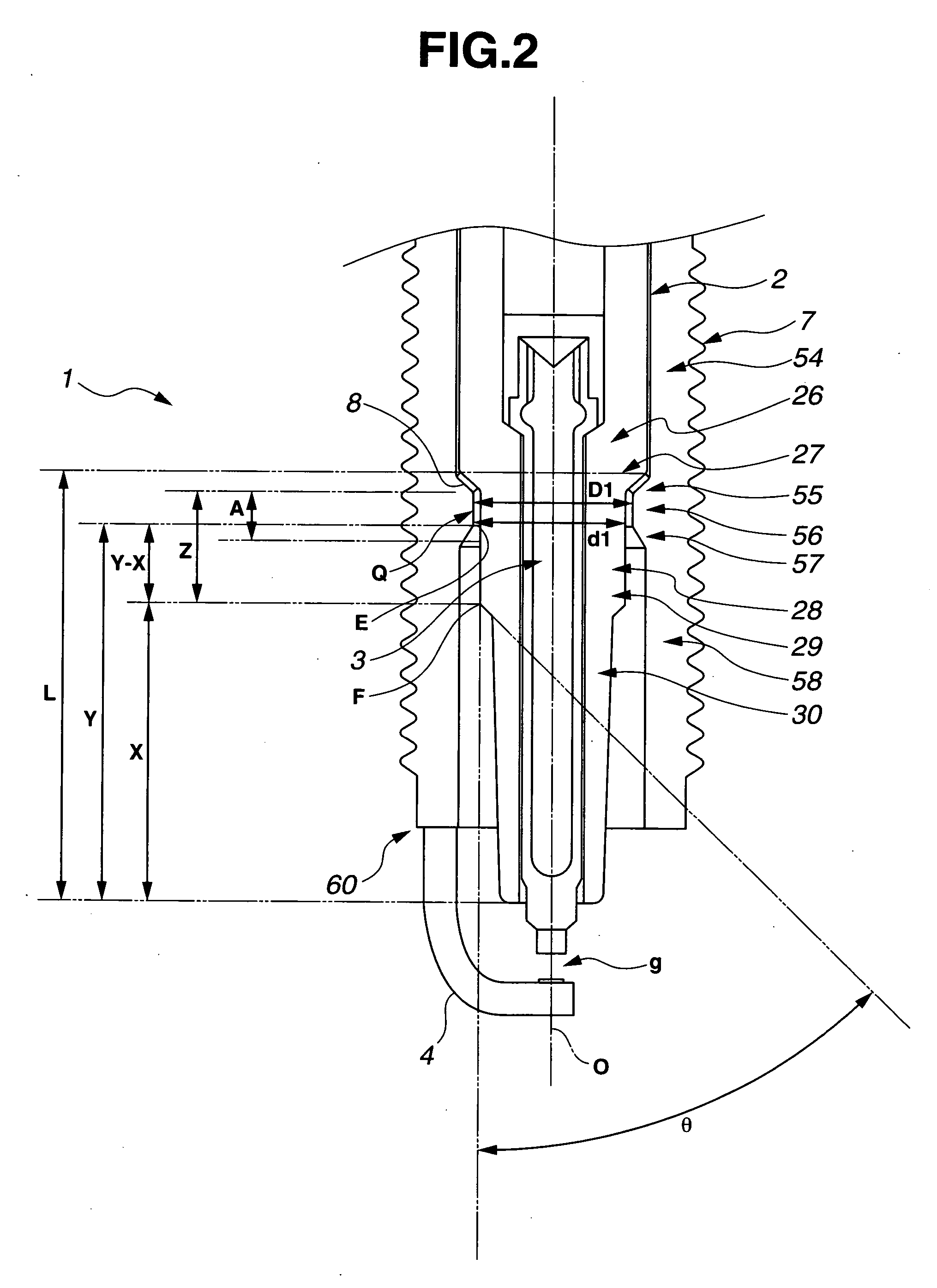
[0073] First, a pre-delivery test of the spark plug 100, depending upon a variation of the clearance β will be described with reference to FIGS. 2 to 4. FIG. 4 is a graph showing the result of the pre-delivery test of the spark plug 100 depending upon a variation of a minimum clearance β′. In the meantime, the test conditions of the pre-delivery test are as follows.

Test Conditions of Pre-Delivery Test

[0074] Engine: 4-cycle DOHC engine having a displacement 2.0 liters [0075] Fuel: lead-free regular gasoline [0076] Oil: 5W-30 [0077] Room temperature: −10° C. [0078] Coolant temperature: −10° C. [0079] Test pattern: JIS D1606 pattern (“method of testing the suitability of an automotive spark plug for use with an engine”) [0080] In the meantime, the pattern of JIS D1606 simulates travel for delivery of a vehicle in a cold season.

[0081] First, assuming that D′1 denotes the outer diameter of the metallic shell smaller diameter portion 56 shown in FIG. 2 and d′1 denotes the inner diamet...

example 2

[0084] Then, the result of a heat resistance test of the spark plug 100, depending upon a variation of the length A of the clearance β will be described with reference to FIGS. 2 to 5. FIG. 5 is a graph showing the result of the heat resistance test of the spark plug 100, depending upon a variation of the length A of the clearance β. In the meantime, the test conditions of the heat resistance test are as follows.

Test Conditions of Heat Resistance Test

[0085] Engine: 4-Cycle DOHC Engine Having a Displacement 1.6 liters [0086] Fuel: lead-free high octane gasoline [0087] Room temperature / humidity: 20° C. / 60% [0088] Oil temperature: 80° C. [0089] Test pattern: engine speed of 5500 rpm, WOT (for two minutes) [0090] WOT means wide open throttle.

[0091] Test examples of the spark plugs 100 in which the lengths A by which the clearance β was attained in the space Q were set to 1 to 7 mm, respectively, were prepared. The engine was operated with the above-described test pattern for the hea...

example 3

[0094] Then, the pre-delivery endurance test of the spark plug 100, depending upon a variation of the length A of the clearance β will be described with reference to FIGS. 2 to 6. FIG. 6 is a graph showing the result of the pre-delivery test of the spark plug 100, depending upon a variation of the length A of the clearance β.

[0095] In the pre-delivery test, test examples of the spark plug 100 in which the lengths A for obtaining the clearance of less than 0.45 mm were set to 1 to 7 mm, respectively, were prepared. The traveling pattern of the above-described JIS D1606 was repeated as a single cycle until the insulation resistance of the spark plug 100 became 10MΩ or less. The result is shown by the solid line in FIG. 6. In the meantime, the length of the metallic shell smaller diameter portion 56 was 1.5 mm, the length from the J portion to the front end of the metallic shell 1 was 12.9 mm, and the minimum clearance β′ was 0.4 mm. In FIG. 6, the ordinate indicates the length A, and...


PUM


Abstract

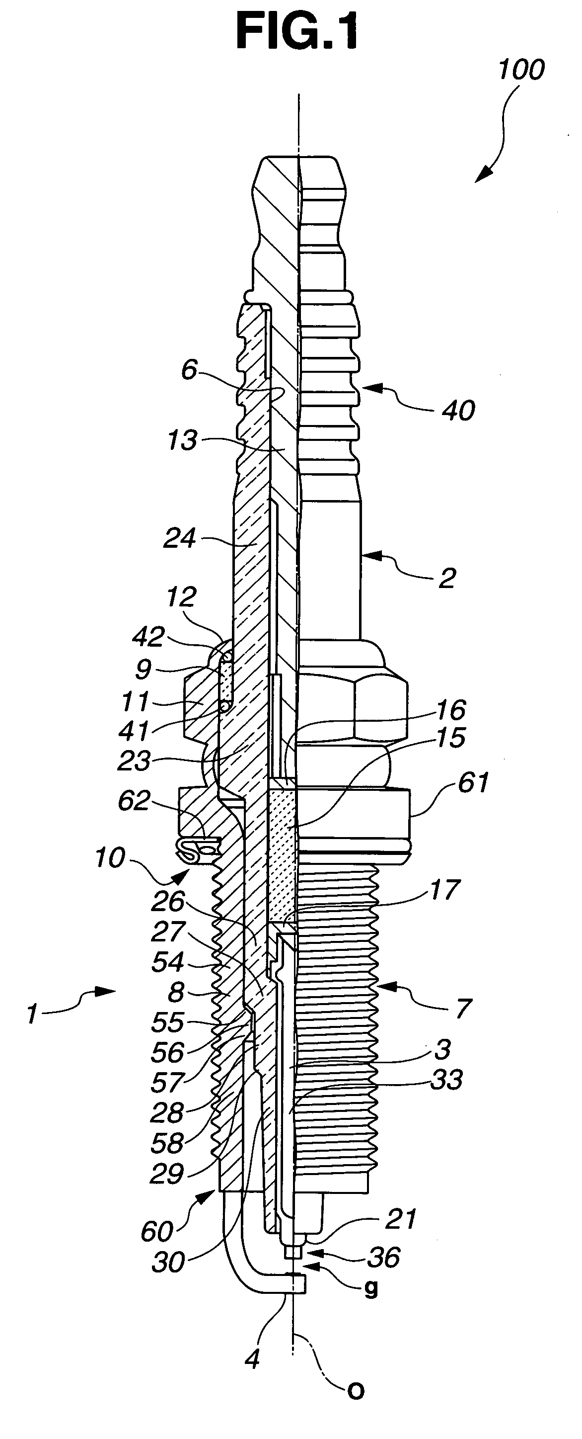
There is provided a spark plug wherein an insulator and a metallic shell, when observed in a section made by a plane including an axis of a spark plug, have therebetween a gap of less than 0.45 mm at a more front end side than an engagement position of a packing and a first insulator stepped portion, and the gap is provided axially from a most front end side engagement position of the packing and a first insulator stepped portion as a starting point to a finishing point that is apart from the starting point by 1.2 mm or more toward the front end side while being apart from a front end surface of the metallic shell by 7.9 mm or more toward a rear end side.

Description

TECHNICAL FIELD [0001] This invention relates to a spark plug for an internal combustion engine and particularly to a spark plug having a heat resistance and a fouling resistance. BACKGROUND TECHNIQUE [0002] Heretofore, since in a spark plug used for ignition in an internal combustion engine such as an automotive gasoline engine, gasoline and air are mixed and combustion in a short time within a combustion chamber at an engine head, incomplete combustion is liable to be caused to allow carbon or the like to be adhered to a front end portion of an insulator of the spark plug, thus being causative of fouling. When a large amount of carbon is adhered to the front end portion of the insulator of the spark plug, spark is not produced at the front end of the spark plug but a leakage (electric leakage) phenomenon in which spark is produced at a different portion to which carbon is adhered. On the other hand, the carbon has a property of all being burned out when heated up to about 520° C. ...

Claims


Application Information

Patent Timeline
IPC IPC(8): H01T13/20H01T13/16H01T13/34H01T13/36
CPCH01T13/16H01T13/36
Inventor KUKI, HIROAKISUZUKI, AKIRAMATSUBARA, YOSHIHIROMORI, KAZUHIKO
Owner NGK SPARK PLUG CO LTD
Learn More