Data processing apparatus and method thereof
a data processing apparatus and color space technology, applied in the field of data processing techniques in color space conversion of image data, can solve the problems of poor cost performance and large memory size, and achieve the effect of improving the cost performance of processing using lu
- Summary
- Abstract
- Description
- Claims
- Application Information
AI Technical Summary
Benefits of technology
Problems solved by technology
Method used
Image
Examples
first embodiment
[0037] 1. Hardware Arrangement of Information Processing Apparatus
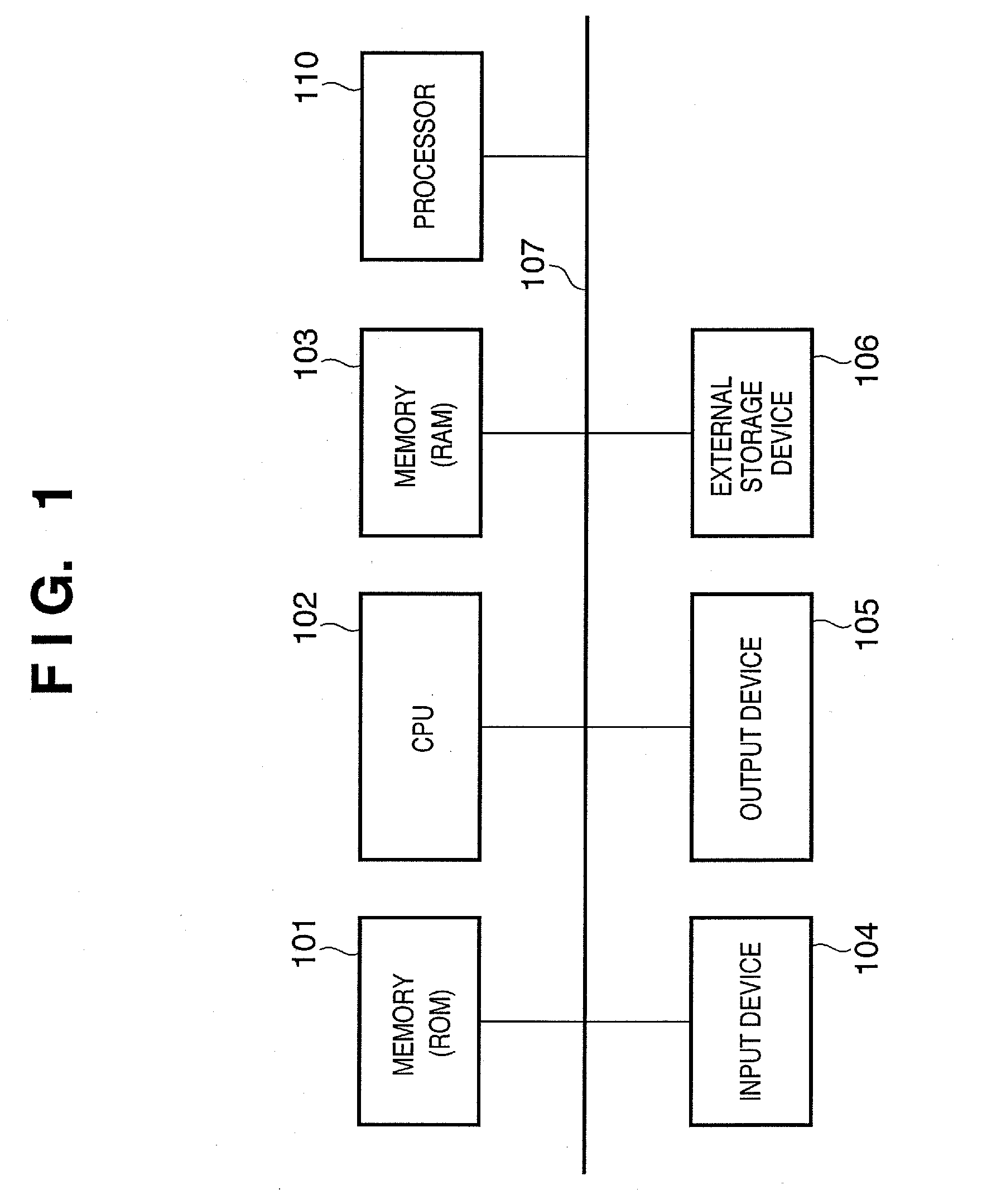
[0038]FIG. 1 is a block diagram showing the hardware arrangement of an information processing apparatus according to the first embodiment of the present invention.
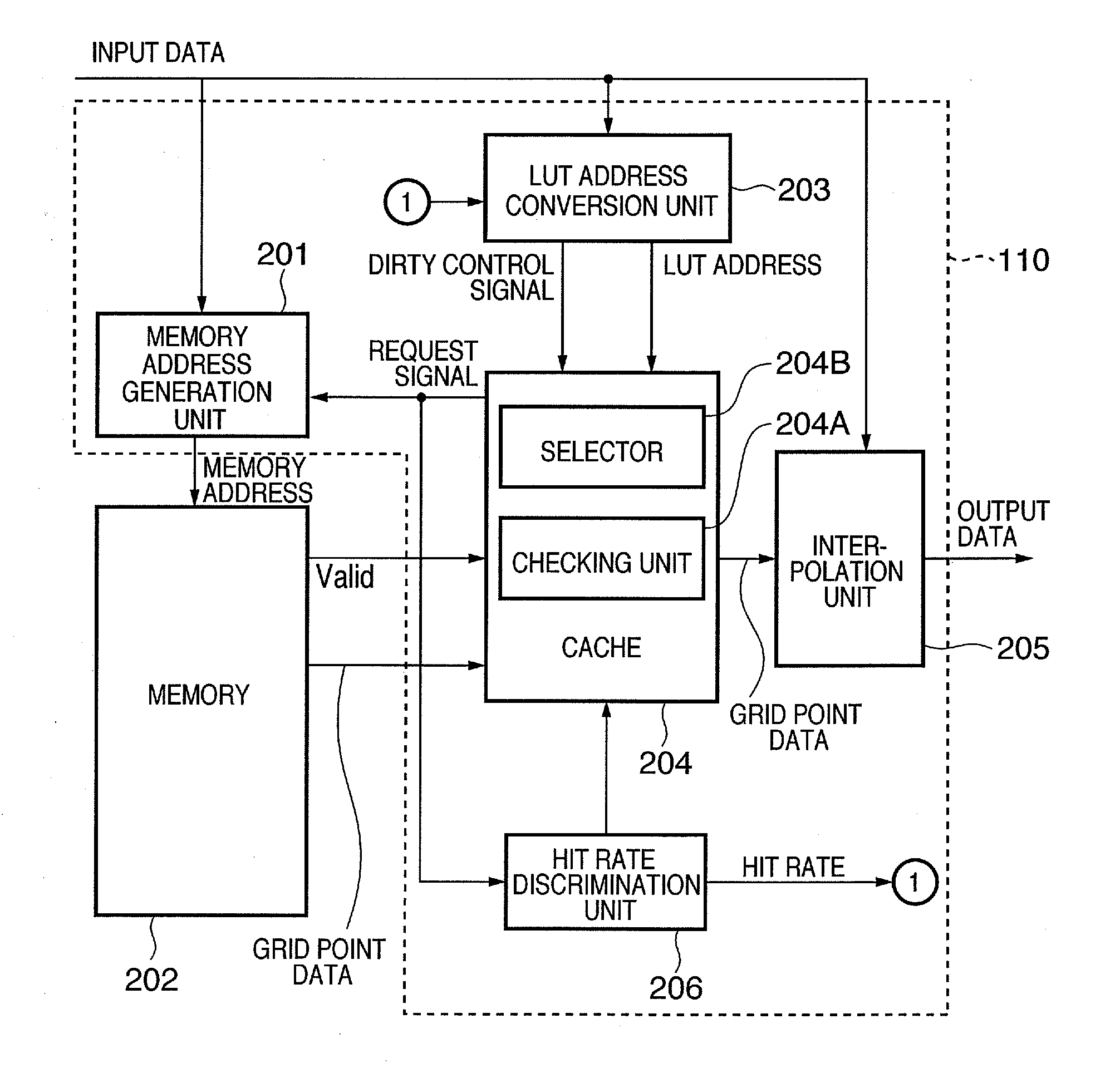
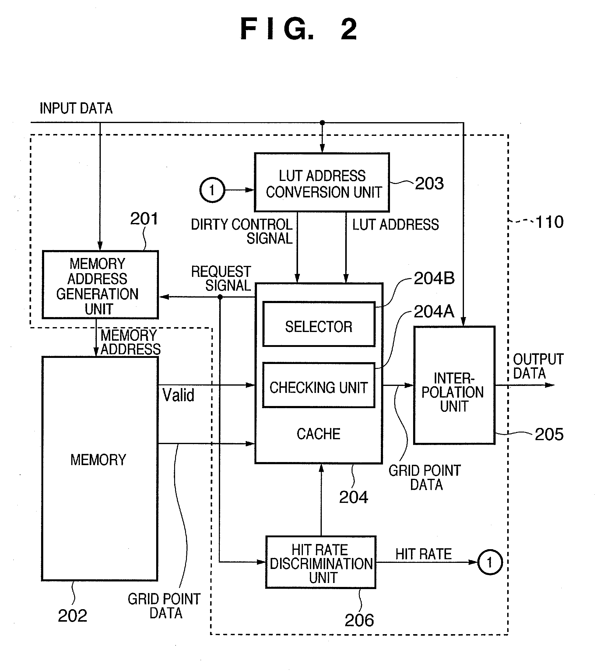
[0039] Referring to FIG. 1, reference numeral 101 denotes a memory (ROM); 102, a CPU; 103, a memory (RAM); 104, an input device; 105, an output device; 106, an external storage device; and 107, a bus. The ROM 101 stores control programs required to implement the information processing functions according to this embodiment and data used in these control programs. These control programs and data are loaded onto the memory 103 as needed via the bus 107 under the control of the CPU 102, and are executed by the CPU 102. Reference numeral 110 denotes a processor which implements a color space conversion function and an LUT address conversion function, as will be described later.
[0040] The input device 104 is used to input various kinds of information. Assume t...
embodiment
5. Embodiment
[0085] An embodiment of the LUT address conversion processing in the information processing apparatus according to this embodiment will be described below. As an embodiment, an LUT address A1 output from the bit order converter 304 is defined as follows: [0086] LUT address A1=[b14, b13, b12, b11, b10, b9, b8, b7, b6, b5, b4, b3, b2, b1, b0]
[0087] Note that the number if‘[]’ represents 1 bit, and ‘,’ represents bit concatenation to have the left end as the MSB and the right end as the LSB. Eight bits (b14, b13,. . . , b7) define the tag of the LUT address, and seven bits (b6, b5, . . . , b0) define the index of the LUT address.
[0088]FIG. 6 is a timing chart of the LUT address output from the bit order converter 304, and that stored in the address register 321. An LUT address A0 stored in the address register 321 at time n+1 in FIG. 6 is defined as follows:
[0089] LUT address A0=[r14, r13, r12, r11, r10, r9, r8, r7, r8, r5, r4, r3, r2, r1, r0]
[0090] Therefore, at time n+...
second embodiment
[0098] The first embodiment generates the address conversion signal from all bits (e.g., 15 bits) of the LUT address. However, the present invention is not particularly limited to this.
[0099] For example, in a mode of filling a cache in a predetermined unit (to be referred to as a “line” hereinafter) to improve the fill efficiency of the cache, the number of entries of a tag memory that stores cache tags can be reduced. For example, if the predetermined unit is “16”, b=4, and lower 4 bits are reduced from the address input of the tag memory (such bits will be referred to as burst bits hereinafter).
[0100] Hence, the LUT address excluding the burst bits may be input to the LUT address comparator 302. That is, the contents of an address register having the bit width of the LUT address excluding the burst bits may be compared with the LUT address excluding the burst bits, and an address conversion signal may be generated based on the change frequency counters 311 as many as the number...
PUM
 Abstract
Description
Claims
Application Information
 - R&D
- Intellectual Property
- Life Sciences
- Materials
- Tech Scout
- Unparalleled Data Quality
- Higher Quality Content
- 60% Fewer Hallucinations
Browse by: Latest US Patents, China's latest patents, Technical Efficacy Thesaurus, Application Domain, Technology Topic, Popular Technical Reports.
© 2025 PatSnap. All rights reserved.Legal|Privacy policy|Modern Slavery Act Transparency Statement|Sitemap|About US| Contact US: help@patsnap.com


