Endovascular tissue removal device

a tissue removal and endovascular technology, applied in the field of endovascular aortic valve replacement, can solve the problems of inconvenient operation, inconvenient use, and inability to provide very precise cutting, and achieve the effect of eliminating the need for precise pressure control, reducing the need for resection, and high rotation ra

Inactive Publication Date: 2007-06-07
RUDKO ROBERT I +2
View PDF65 Cites 66 Cited by
  • Summary
  • Abstract
  • Description
  • Claims
  • Application Information

AI Technical Summary

Benefits of technology

[0013] It is a further object of this invention to provide a tissue cutter which provides effective resection even if the valve is heavily calcified or has fibrotic tissue.
[0014] It is a further object of this invention to provide such a tissue cutter which does not require a high rate of rotation.
[0015] It is a further object of this invention to provide such a tissue cutter which eliminates the need for precise pressure control.

Problems solved by technology

The problem with such a system is that the tissue cutting blade assembly is less than optimal and does not provide very precise cutting especially given the fact that the valve is made of both soft and hard tissue because it is heavily calcified or contains fibrotic tissue.
If too much tissue is cut in certain areas, for example, the aorta can be permanently damaged.
Moreover, the existing valve typically fails because of calcification of the valve resulting in stenosis or insufficiency.
Using cutting blades for valve resection and an improper orientation or improper pressure on the cutting blades or the wrong rate of rotation can result in too little or too much tissue removal and / or imprecise cutting and / or blade buckling or binding as the blades alternately contact soft and hard (calcified) tissue.
U.S. Pat. No. 5,554,185 discloses an inflatable prosthetic cardiovascular valve but does not disclose any specific method of resecting the existing or native valve.
In many cases, however, such a procedure can not be carried out due to the poor condition of the native valve.
And, because the native valve occupies space, the largest aperture possible by the replacement valve may not provide sufficient blood flow.

Method used


Image

  • Endovascular tissue removal device
  • Endovascular tissue removal device
  • Endovascular tissue removal device

Examples


Embodiment Construction

[0029] Aside from the preferred embodiment or embodiments disclosed below, this invention is capable of other embodiments and of being practiced or being carried out in various ways. Thus, it is to be understood that the invention is not limited in its application to the details of construction and the arrangements of components set forth in the following description or illustrated in the drawings.

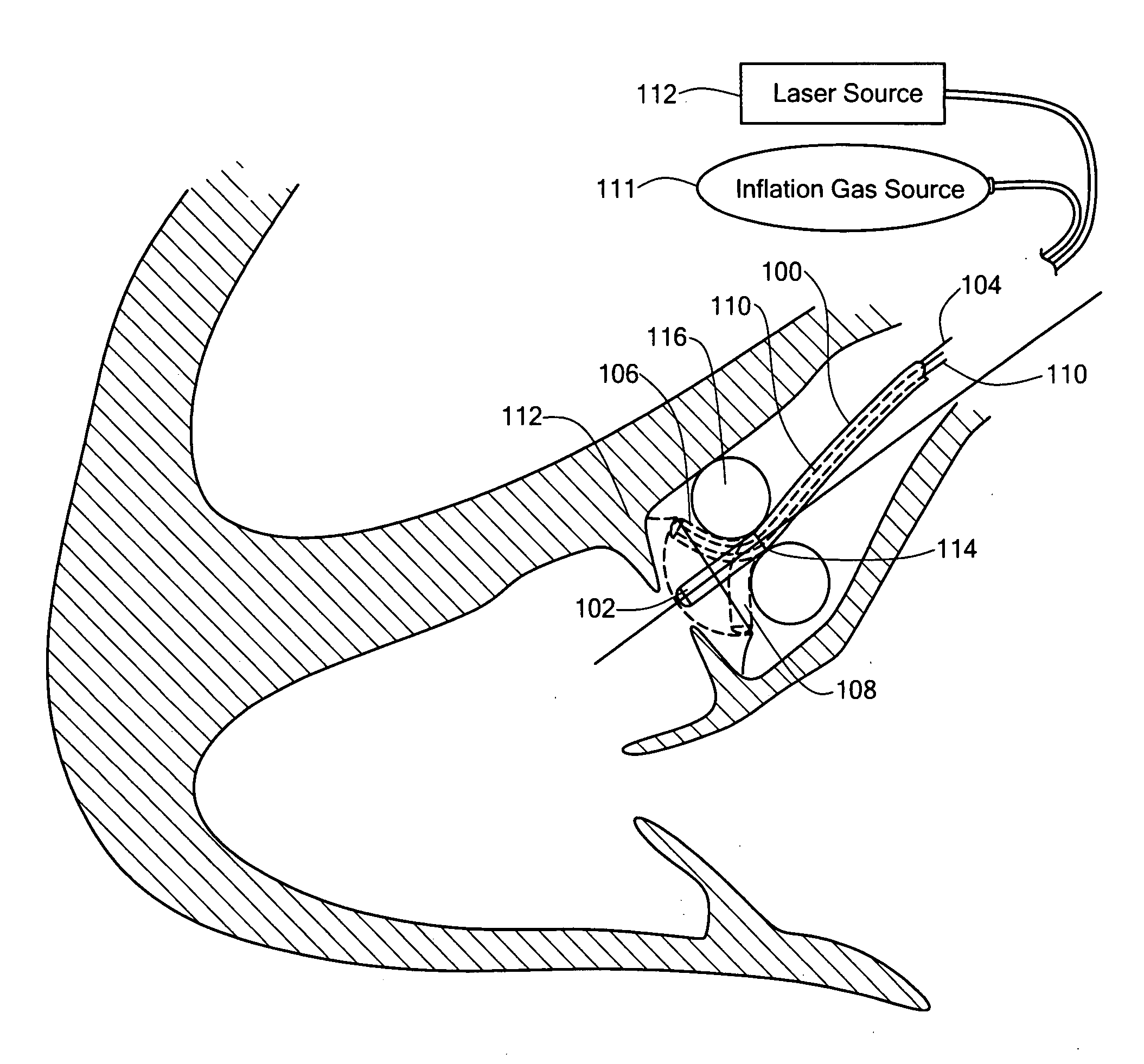
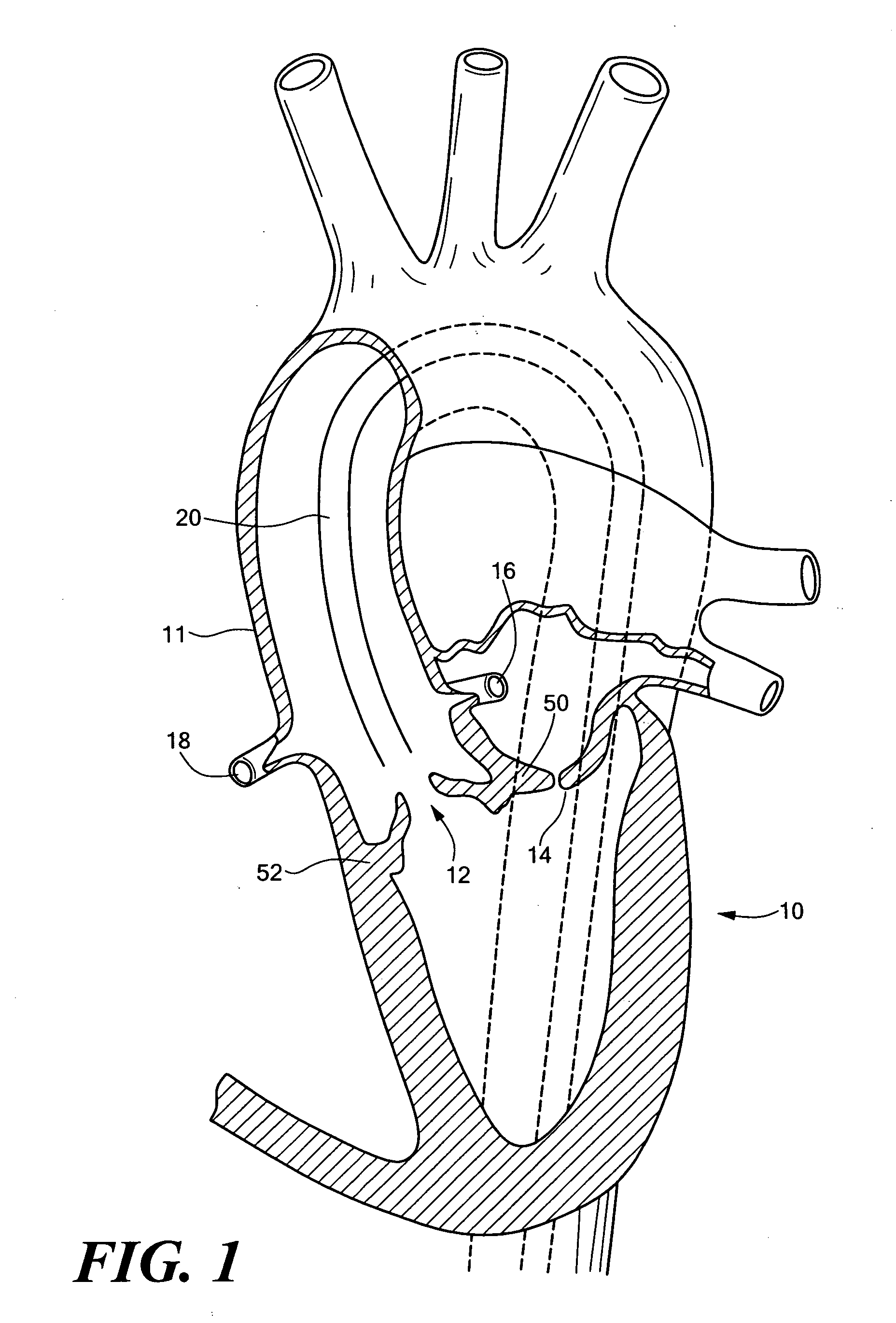
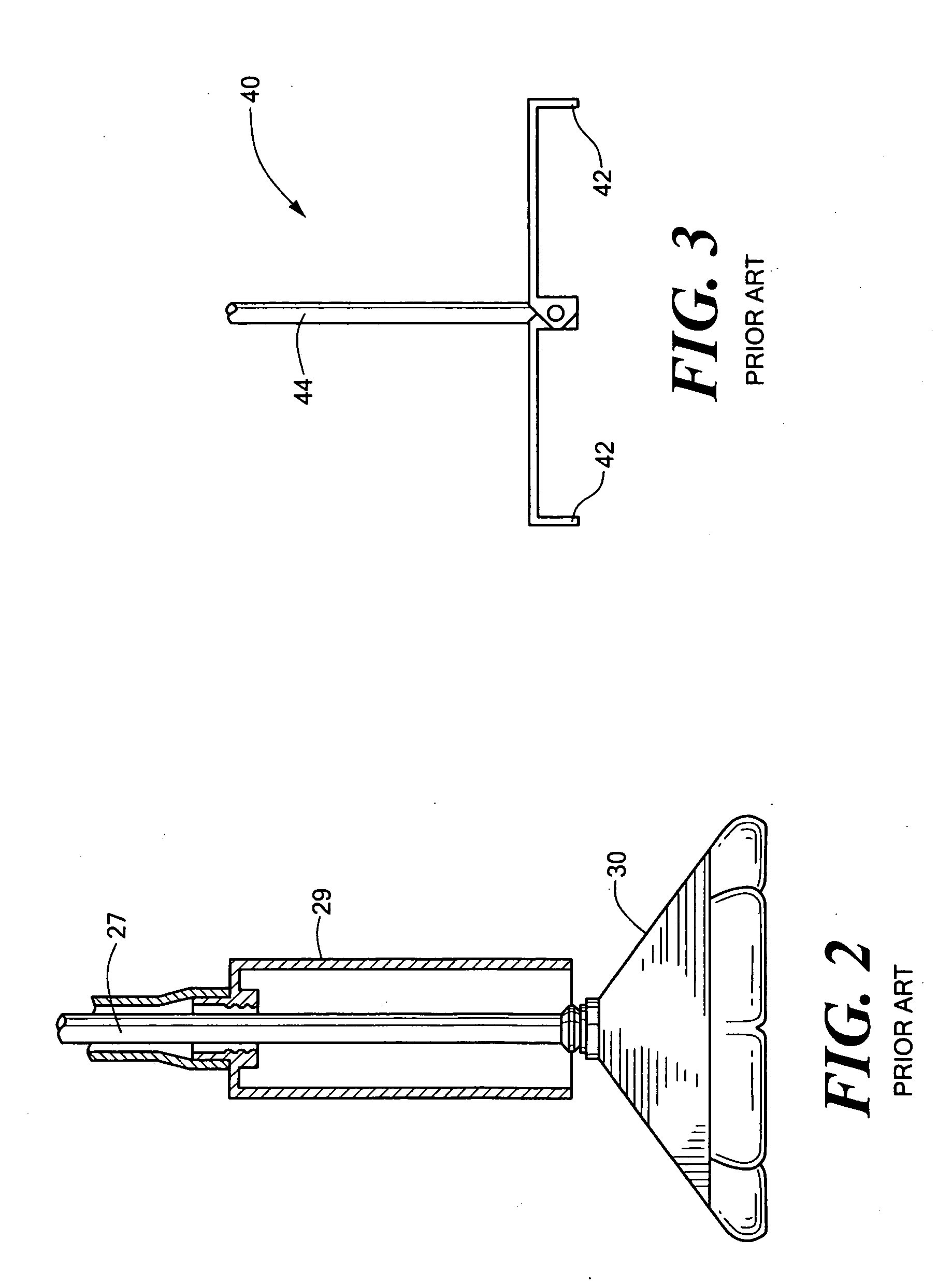
[0030]FIG. 1 schematically shows heart 10 with aorta 11, aortic valve 12, mitral valve 14, and coronary arteries 16 and 18. The idea behind percutaneous valve replacement surgery is to deliver a catheter 20 proximate valve 12 to resect it and to secure a replacement prosthetic valve in place. Resecting the native valve, however, is problematic. Those skilled in the art have devised inflatable barriers such as barrier 30, FIG. 2 used to trap tissue during resection. See also U.S. Pat. No. 6,287,321 and Published Patent Application No U.S. 2002 / 0095116 A1. Barrier 30 traps any tissue cut du...


PUM


Abstract

An endovascular tissue removal device including a lumen with a distal steerable tip portion extending from a joint portion, registration means for holding the joint portion fixed in place in the vasculature, and a source of ablation energy in communication with the lumen whereby tissue can be resected by ablation energy as the tip portion is steered within the vasculature.

Description

RELATED APPLICATIONS [0001] This is a Divisional application of U.S. patent application Ser. No. 10 / 628,794, filed on Jul. 28, 2003, hereby incorporated by reference herein.FIELD OF THE INVENTION [0002] This invention relates to endovascular aortic valve replacement. BACKGROUND OF THE INVENTION [0003] Currently, replacement of a malfunctioning heart valve is accomplished by a major open-heart surgical procedure requiring general anesthesia, full cardio-pulmonary bypass with complete cessation of cardio-pulmonary activity, and a long period of hospitalization and recuperation. In most cases, the native valve is resected (cut-out) and the replacement valve then installed. [0004] As an alternative to open heart surgery, those skilled in the art have attempted to devise systems for endovascular heart valve replacement to overcome the disadvantages associated with open-heart surgery. U.S. Pat. No. 5,370,685, for example, discloses a procedure device capsule connected to a tube and delive...

Claims


Application Information

Patent Timeline
Patent Type & Authority Applications(United States)
IPC IPC(8): A61B18/18A61B17/00A61B17/22A61B18/24
CPCA61B18/24A61B2017/00243A61B2017/22069A61B2017/22097A61B2018/2238A61B2018/00369
Inventor RUDKO, ROBERT I.TAUSCHER, MARK R.YEOMANS, RICHARD P. JR.
Owner RUDKO ROBERT I
Why Eureka
Try Eureka