Variably delayable transmission of packets between independently clocked source, intermediate, and destination circuits while maintaining orderly and timely processing in one or both of the intermediate and destination circuits

a technology of packet transmission and delay, which is applied in the direction of generating/distributing signals, data switching networks, instruments, etc., can solve the problems of undesired phase skew between parts, inability to keep all parts synchronized to a common seed clock, and skew of clocks, etc., to achieve faster traffic throughput, increase volume, and increase size and speed

a technology of packet transmission and delay, which is applied in the direction of generating/distributing signals, data switching networks, instruments, etc., can solve the problems of undesired phase skew between parts, inability to keep all parts synchronized to a common seed clock, and skew of clocks, etc., to achieve faster traffic throughput, increase volume, and increase size and speed

US20070130246A1Inactive Publication Date: 2007-06-07MICROSEMI STORAGE SOLUTIONS US INC

Image

  • Variably delayable transmission of packets between independently clocked source, intermediate, and destination circuits while maintaining orderly and timely processing in one or both of the intermediate and destination circuits
  • Variably delayable transmission of packets between independently clocked source, intermediate, and destination circuits while maintaining orderly and timely processing in one or both of the intermediate and destination circuits
  • Variably delayable transmission of packets between independently clocked source, intermediate, and destination circuits while maintaining orderly and timely processing in one or both of the intermediate and destination circuits

Examples


embodiment 100

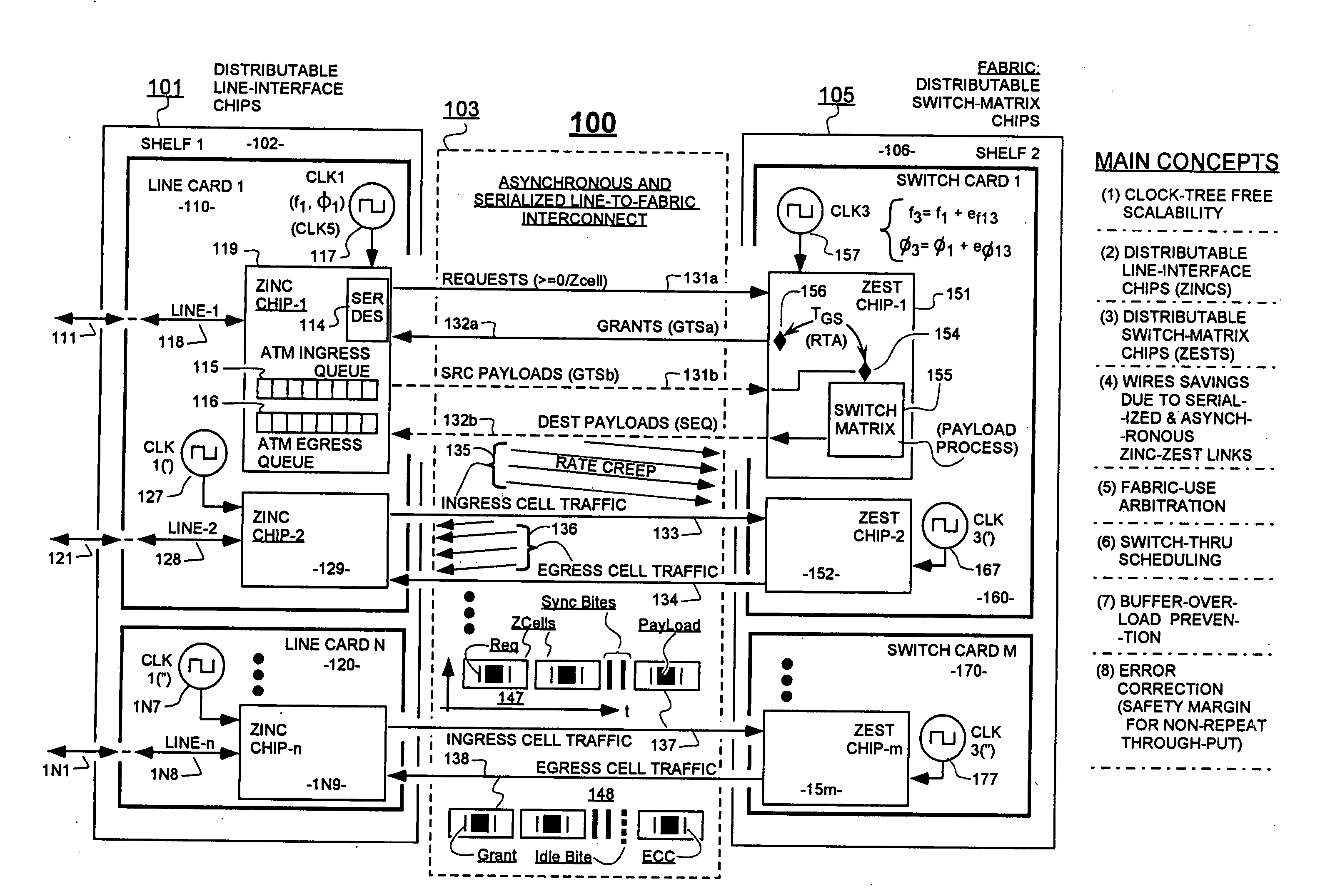
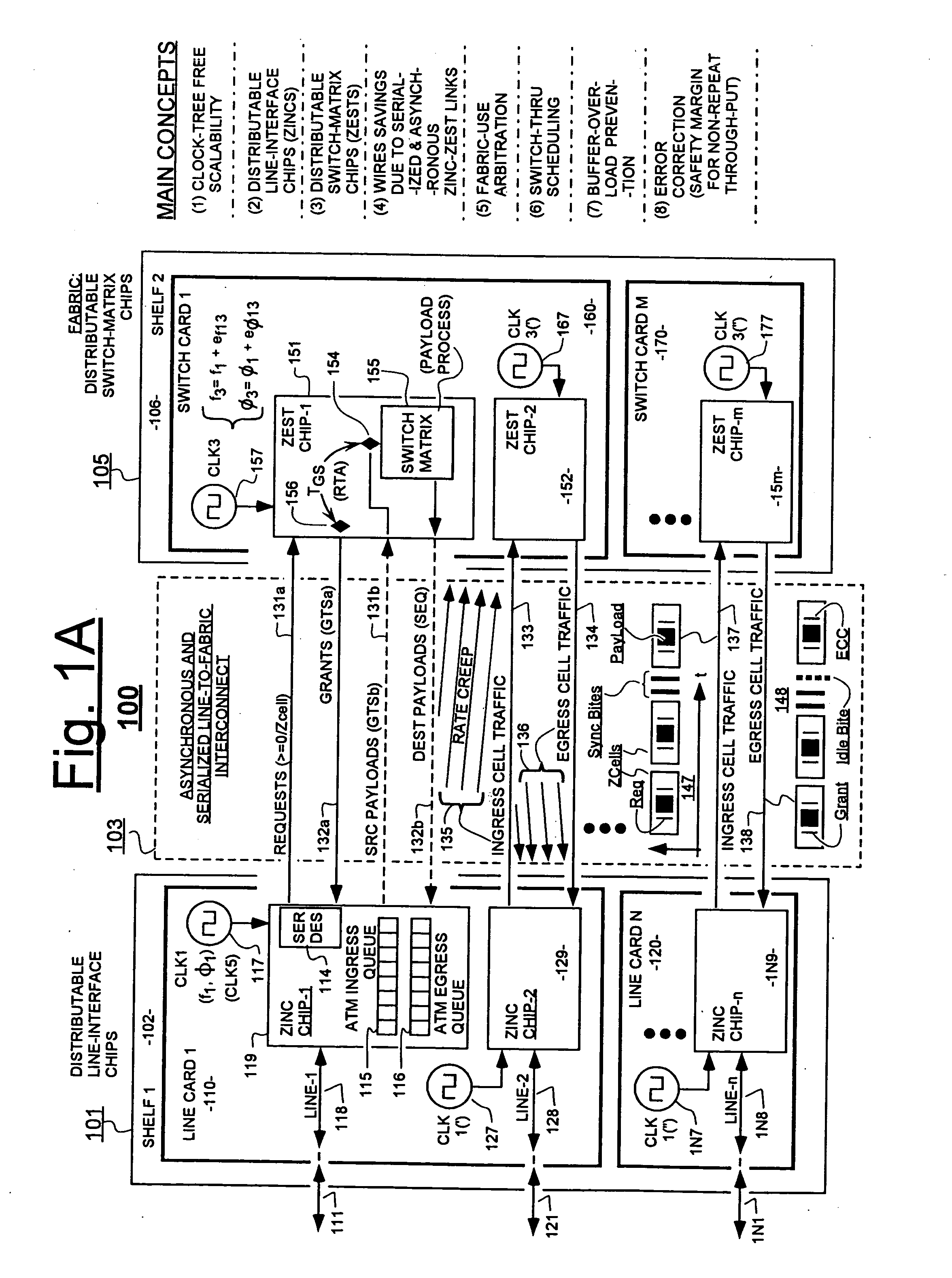
[0088] The dynamic back-pressure technique mentioned above solves the problem of excessive rates of incoming request fields overwhelming a slow-clocked ZEST chip. It does not, however, solve the rate-differential problem going the other way; where a faster-clocked ZEST is sending grants (132a) back to a slower clocked, source ZINC. Nor does it solve the rate-differential problem that occurs when a faster-clocked ZEST is sending egressing payloads (132b) to a slower clocked, destination ZINC. In one embodiment, both of the latter problems are simultaneously solved on a static basis by periodically inserting an idle state into the ZEST ticks (see graph 206 of FIG. 2A) and thereby constraining the effective ZCell-processing rates of all ZEST units, including the fastest-clocked one of such ZEST units, so that the averaged-over-long-time rates of even the fastest-clocked ZEST unit can be no faster than the averaged-over-long-time cell processing-rate of the slowest-clocked one of the ZI...

embodiment 200

[0128]FIG. 2B shows more details of a first RTA-compliant embodiment 200′ by way of which this concept may be carried out. At the time that a grant is locally given by a request processor 252′ within ZEST unit 253′, the request processor 252′ should know several important things. It should know the identity of the physical source line (one of lines 255.1 through 255.N) through which the payload will be later coming into the payload processing unit 255′ because this is part of the later-in-time processing event that the request processor 252′ should be scheduling for at an earlier time. The request processor 252′ should also know at grant time what the identity is of the corresponding physical output line or lines (shown as horizontal lines 255a-n in unit 255′ of FIG. 2B) from which processed-payloads will emerge from the payload processing unit 255′. Moreover, the request processor 252′ should also know the scheduled time slot at which the payload-processing will be carried out. It ...

embodiment 600

[0151] Referring to FIG. 6, we now consider a view of a system embodiment 600 that handles ZEST-to-ZINC egress traffic. It is assumed here that an in-ZEST grant scheduling algorithm running in a request processor 652 has already injected, at a first time point, t01, granting information 625g into a ZCell 625 that was dispatched back toward the requesting ZINC chip. The physical source identification 625s used in the grant scheduling was stored into GSQ 649. The grant scheduling algorithm may have used one or more of the busy indications 672 from pre-assigned egress lines, routing priority codes, and request aging information to establish what payload processings will take place RTA ticks after each grant. When the grant-carrying ZCell 625 arrived at a corresponding, request-making ZINC chip, the GTSa information in ZCell 625 was copied or otherwise uniquely transformed, as indicated at 626, to define the GTSb code in the payload section of a ZINC-to-ZEST ZCell and combined together ...


PUM


Abstract

In a system having independently-clocked job-performing circuits (e.g., payload processors) and independently-clocked job-ordering circuits (e.g., request and payload suppliers), coordinating mechanisms are provided for coordinating exchanges between the independently-clocked circuits. The coordinating mechanisms include those that use transmitted time-stamps for scheduling contention-free performances within the job-performing circuits of requested jobs. The coordinating mechanisms additionally or alternatively include static and dynamic rate constraining means that are configured to prevent a faster-clocked one of the independently-clocked circuits from overwhelming a more slowly-clocked other of the independently-clocked circuits. In one implementation, independently-clocked telecommunication-shelves house a distributed set of line cards and switch cards. An asynchronous interconnect is provided between the independently-clocked shelves for carrying job requests and payload data between the distributed line cards and the distributed switch cards. The multi-shelf system is scalable and robust because additional or replacement line and switch cards may be inserted into one or another of the independently-clocked shelves as desired and because a unified clock-tree is not needed for synchronizing activities within the interconnected, but independently clocked shelves.

Description

1. FIELD OF DISCLOSURE [0001] The present disclosure of invention relates generally to transmission between circuits of digital packets or cells or otherwise-framed sets of data, and to synchronized processing of the transmitted digital packets / cells / data-sets within the circuits, where the processing is such as may occur in high-speed telecommunication systems. [0002] The disclosure relates more specifically to rate-disparity and synchronization problems that can develop when attempts are made to switch and / or otherwise process high-rate digital traffic in a timely and orderly manner while moving packets: (1) from a packet sourcing circuit that operates in synchronism with a first clock, (2) over an interconnect that may have variable delay (spatially and / or temporally) to a packet processing circuit that operates in synchronism with an independent second clock, and (3) over the interconnect (with the possibility of other variable delay) to a packet-sinking circuit {receiving desti...

Claims


Application Information

Patent Timeline
07 Jun 2007
Publication
US20070130246A1
IPC
G06F15/16
CPC
G06F1/14; H04L2012/5674
Inventors
ORNES, MATTHEW D.; BERGEN, CHRIS D.