
A cell culture bioreactor

Active Publication Date: 2007-06-14
SEPRAGEN
View PDF17 Cites 22 Cited by
  • Summary
  • Abstract
  • Description
  • Claims
  • Application Information

AI Technical Summary

Benefits of technology

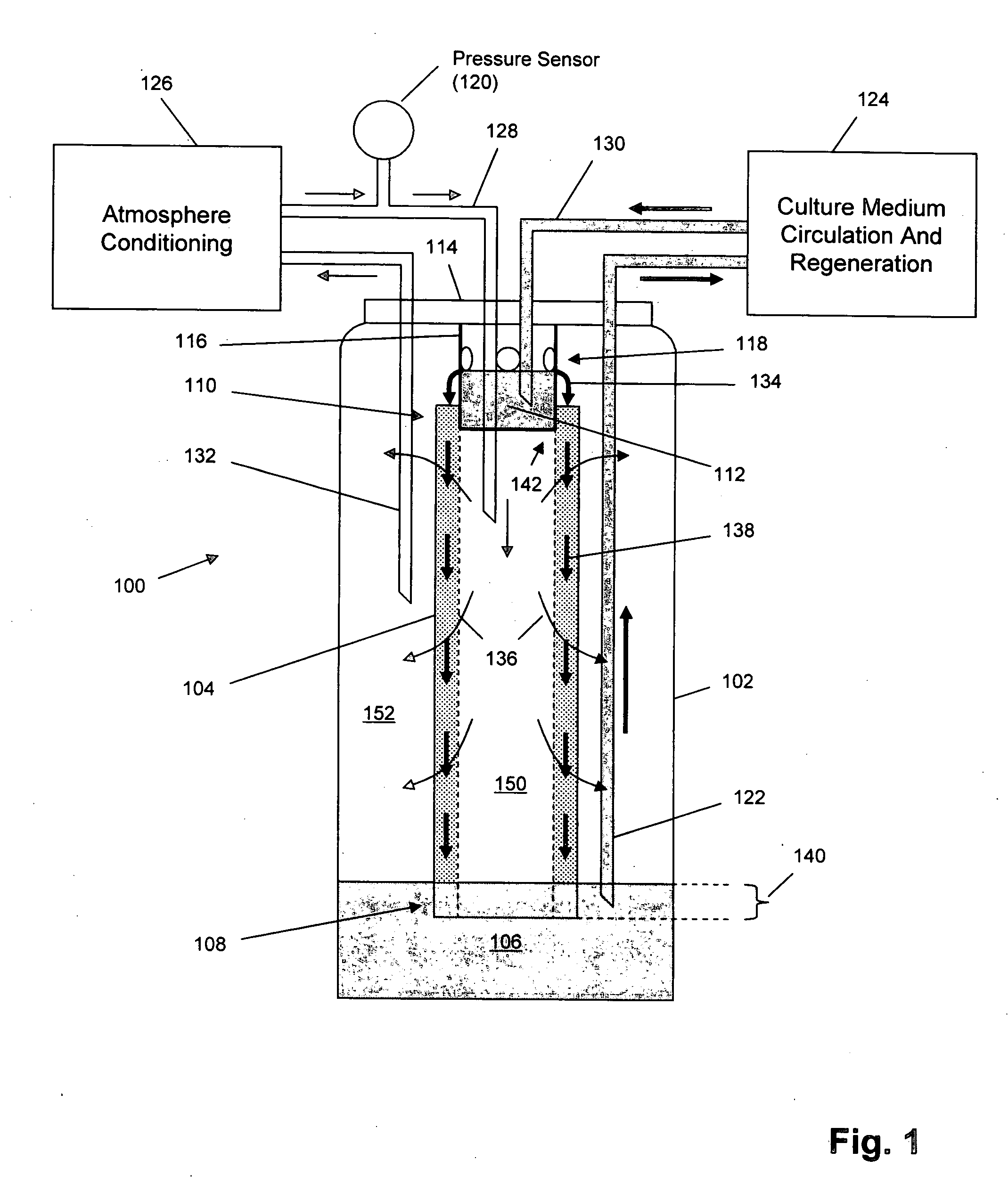
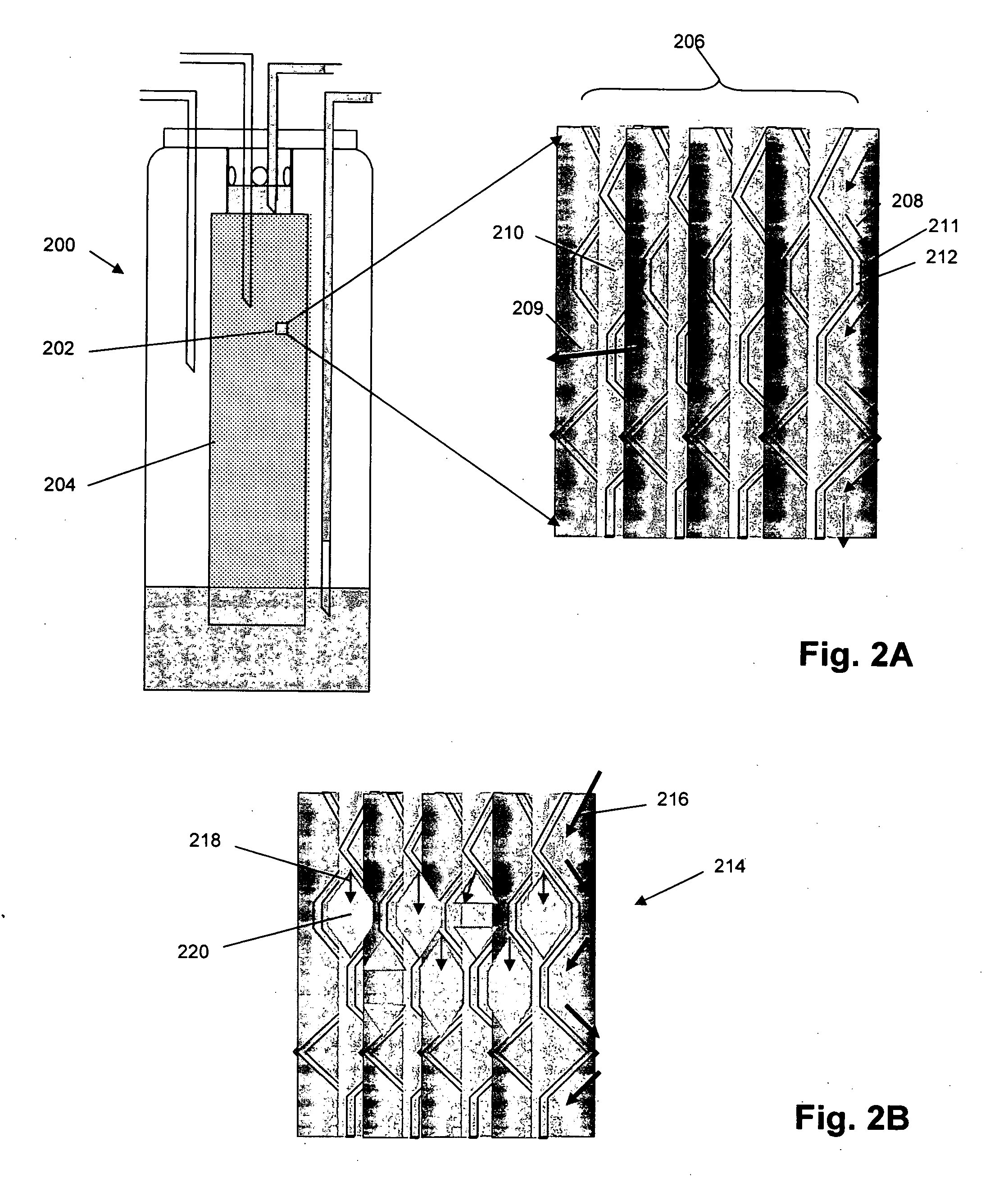
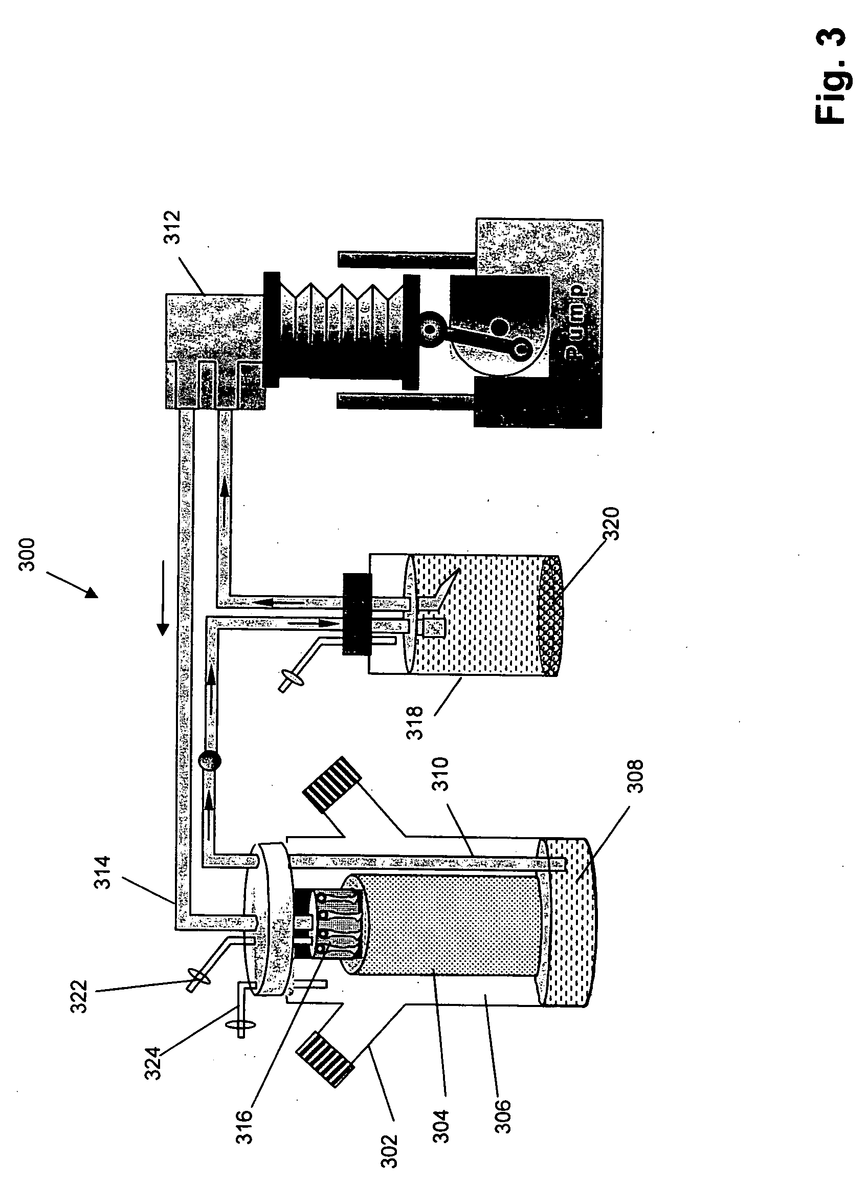
[0021] The bioreactor device of the present invention comprises the following elements: (a) a culture chamber having an inlet, an outlet, and an interior; (b) a support matrix with a top end and a bottom end, mounted in the interior of the culture chamber for holding biological cells on the support matrix, the support matrix comprising a porous material having continuous open pores, such material being formed of interlacing and interconnected fibers and having a non toxic surface suitable as a substrate for biological cells; the continuous open pores of such material permitting substantially equivalent communication with the interior of the culture chamber from any location on the surface of the support matrix; (c) a first reservoir mounted outside the bioreactor for holding a culture medium; (d) a second reservoir for the culture medium supported at the top end of the reservoir directly above the top end of the support matrix; (e) fluid circulation means having a fluid delivery rate for non-turbulently delivering culture medium to the support matrix, such that the culture medium flows in a thin film over substantially the entire surface of the support matrix to the bottom end of the support matrix and the chamber which is then removed or recycled through the outlet; and (f) circulation means for supplying oxygen or other gas or gases, as are suitable for growth of the cells, to the surface of the support matrix and through the support matrix to the interior of the culture chamber.
[0024] In yet another embodiment, the present invention provides a method for high performance cell culture comprising the following steps: (a) providing a culture chamber having an inlet, an outlet, an interior, and a support matrix mounted in the interior for holding biological cells, the support matrix comprising a porous material having continuous open pores, such material being formed of interlacing and interconnected fibers or porous foam, and having a non toxic surface suitable as a substrate for biological cells, the continuous open pores of such material permitting substantially equivalent communication with the interior of the culture chamber from any location on the surface of the support matrix; (b) introducing a culture medium containing biological cells into the culture chamber and allowing the biological cells to become immobilized on the support matrix; and (c) non-turbulently delivering a flow of culture medium to the support matrix, such that (1) the flow of culture medium travels in a thin film over substantially the entire surface of the support matrix to a reservoir at the bottom end of the support matrix and through the outlet, (2) substantially none of the continuous open pores of the support matrix are flooded by the flow of culture medium, (3) circulating fluid reaches the bottom of the support matrix, turbulent free, thus preventing foam formation, and (4) simultaneously flowing a stream of air gently across and through the surface of the support matrix such that there is no back pressure generated by the flow of the medium across the surface of the matrix.

Problems solved by technology

These methods and devices compromise between minimizing shear stress on the cells and oxygenation.
This method is specifically designed for tissue implants, but not for the growth of cells by direct exposure to liquid / air interface.
All these methods suffer from major disadvantages in that they have to continuously compromise between sufficient movement of culture media across cell membranes to provide them nutrients for sufficient growth and, at the same time provide sufficient O2 / CO2 gas exchange rates, without limiting rate of movement of these elements, to minimize shear-stress to the cells.
This is a serious dilemma, and currently “dealt with” by reducing cell density to levels that are supported by the limited gas exchange rates.
They are not suitable for large scale production as they are not directly scalable.

Method used


Image

  • A cell culture bioreactor
  • A cell culture bioreactor
  • A cell culture bioreactor

Examples


Embodiment Construction

[0031] The invention provides a method, system, and device for supporting large-scale continuous, or batch culturing of biological cells, by culturing cells directly on the support matrix. In an alternative mode, the invention also provides a method and device for continuously aerating, and in particular oxygenating a culture medium used to support a bioreactor by acting as a gas exchanger (a “lung”) only, with no cells immobilized on the support matrix. In this aspect cells are NOT grown directly on the “lung”, but are grown, in a conventional bioreactor (i.e. hollow fiber or suspension culture), partitioned from the support matrix. The support matrix oxygenates the culture fluid, but cells are grown in a connected (but partitioned) conventional bioreactor.

[0032] A novel feature of the invention is the simultaneous and continuous oxygenation and nourishment of the biological cells being cultured. This is achieved by the use of a support matrix that is a porous material having cont...


PUM


Abstract

A cell culture bioreactor having a culture chamber for cell growth, a culture medium reservoir mounted externally to the culture chamber, a fluid circulation mechanism for moving culture medium from the reservoir through the culture chamber, and an aerating mechanism for introducing air into and removing air from the culture chamber is provided. The cell culture bioreactor comprises a manifold mechanism mounted at the top end of the culture chamber, a fluid circulation mechanism fluidly connected to the culture medium reservoir, for receiving culture medium from the culture medium reservoir and distributing culture medium into the culture chamber. A support matrix is mounted within the culture chamber in fluid communication with the fluid circulation mechanism with at least a portion of the support matrix contacting the culture medium wherein the culture medium flows from the manifold means in a thin film over substantially the entire surface of the support matrix allowing the biological cells to grow on the support matrix.

Description

[0001] The present application claims benefit of priority of pending provisional patent application Ser. No. 60 / 750,219, filed by Dennis R. Gould and Hriar Kirakossian, on Dec. 14, 2006, titled “Cell Culture Bioreactor”.FIELD OF THE INVENTION [0002] The present invention relates generally to cell culture and more specifically to a novel bioreactor for growing cells for culture and harvesting. BACKGROUND OF THE INVENTION [0003] Pharmacologically significant biological products for research and therapy are manufactured largely using various cell culture technologies (Chu et al., “Current Opinion in Biotechnology” (2201) 12: 180-187). Monoclonal antibodies, recombinant proteins / peptides including vaccines, produced by such technologies, are currently on the market or in active, phased development world wide. World wide demand for large scale cell culture production, therefore, continues to increase. [0004] Currently, the industry standard method for large scale cell culture is suspensi...

Claims


Application Information

Patent Timeline
IPC IPC(8): C12N5/06C12M3/00
CPCC12M23/40C12M29/10C12M25/14
Inventor GOULD, DENNIS RICHARDKIRAKOSSIAN, HRAIR
Owner SEPRAGEN
Learn More