Hot-plug control system and method

a control system and hot plug technology, applied in the direction of electrical equipment, electric digital data processing, instruments, etc., can solve the problems of data loss and service interruption of servers that require time continuity and high reliability, and the pci bandwidth gradually becomes a bottleneck, so as to simplify circuit design and reduce production costs

Active Publication Date: 2007-06-14
INVENTEC CORP
View PDF5 Cites 40 Cited by
  • Summary
  • Abstract
  • Description
  • Claims
  • Application Information

AI Technical Summary

Benefits of technology

[0017] Thus, the hot-plug control system and method of the present invention implements a universal PCI-E hot-plug function that could be applied to different kinds of computer devices by combining peripheral devices using the PCI-E hot-plug technology with a computer device with general construction. Accordingly, there is no need to design a specialized PCI-E hot-plug control chip for a specific computer device, thereby simplifying circuit design and reducing production cost.

Problems solved by technology

To drive a peripheral device, computer devices often need to be restarted and current operations need to be stopped, thereby resulting in complication and inconvenience and even resulting in data loss and service interruption of servers that require time continuity and high reliability.
However, with further development and application expansion of the computer technology, the PCI bandwidth gradually becomes a bottleneck.
This leaves little room for any other peripheral devices to use.
However, the PCI-E hot-plug technology can only be applied to a computer device that is provided with a specialized PCI-E hot-plug control chip produced by Intel Inc. while it is impossible for other computer devices such as those produced by the AMD Inc. to use the PCI-E hot-plug technology, thereby limiting the application of the PCI-E hot-plug technology.

Method used


Image

  • Hot-plug control system and method
  • Hot-plug control system and method
  • Hot-plug control system and method

Examples


Embodiment Construction

[0021] Hereunder, embodiments of the present invention will be described in full detail with reference to the accompanying drawings.

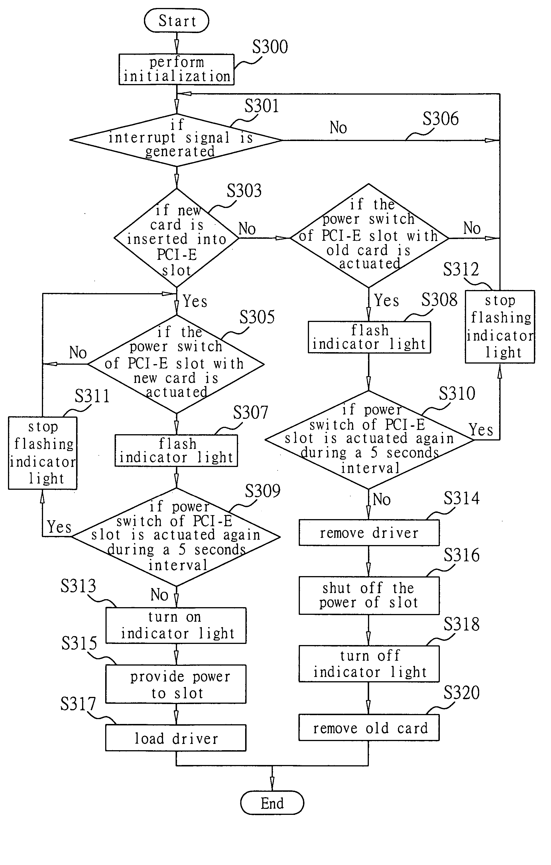
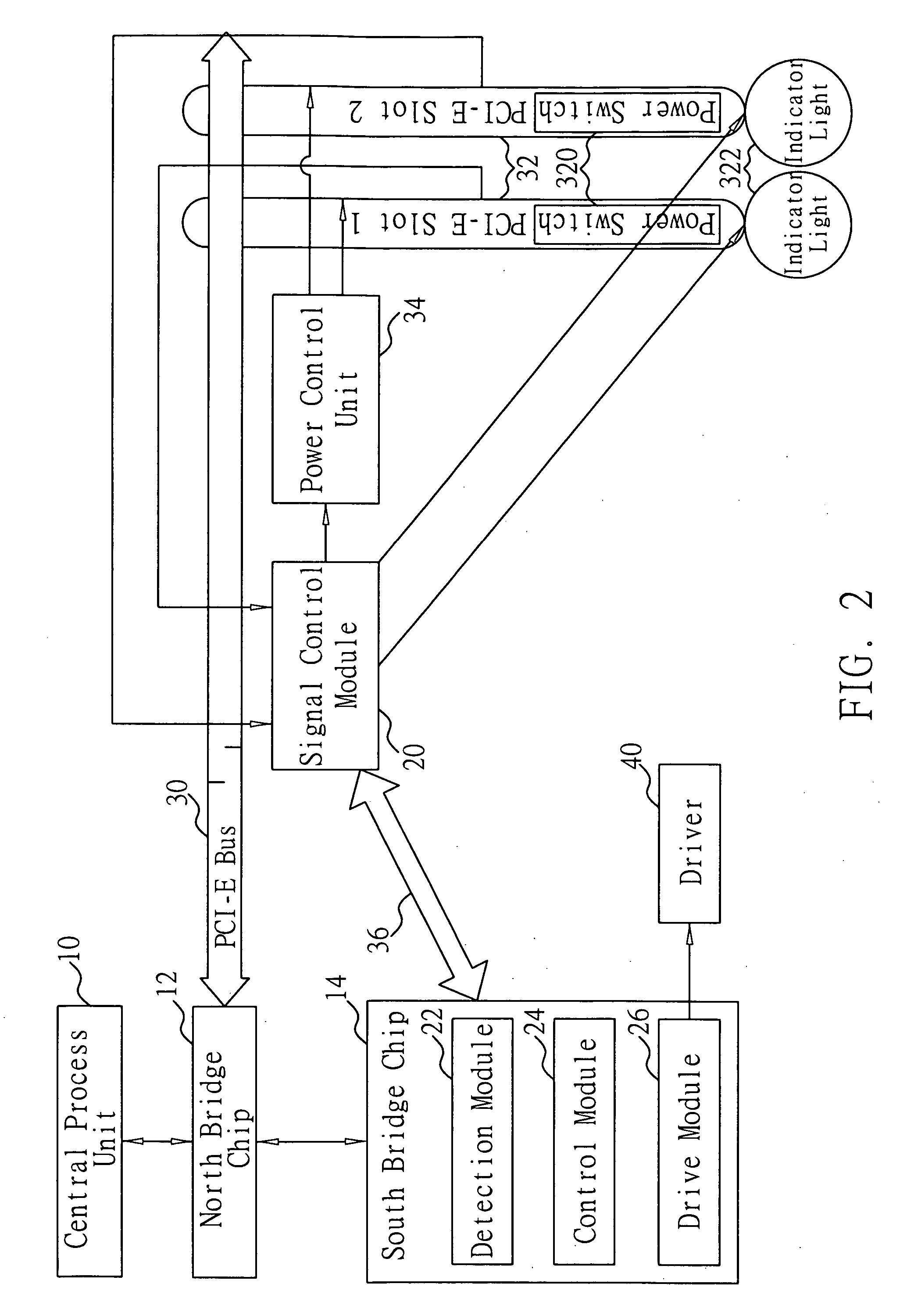
[0022] As shown in FIG. 2, the hot-plug control system of the present invention comprises a signal control module 20, a detection module 22, a control module 24 and a drive module 26. The hot-plug control system is applied in a computer device having traditional components such as a CPU (Central Process Unit) 10, a NB (North Bridge) chip 12 and a SB (South Bridge) chip 14. Meanwhile, the computer device is further provided with a PCI-E (Peripheral Component Interconnect Express) bus 30, at least one PCI-E slot 32 having a power switch 320 and an indicator light 322, a power control unit 34 and a driver 40. The power switch 320 could be a button. The indicator light 322 could be a LED light, which is used to indicate work status of the PCI-E slot 32.

[0023] The signal control module 20 is used to generate an interrupt signal. In the present embodiment, ...


PUM


Abstract

A hot-plug control system and method is applied to a computer device, wherein the computer device is provided with a PCI-E (Peripheral Component Interconnect Express) bus, at least one PCI-E slot having a power switch and an indicator light, a power control unit and a driver. The hot-plug control system at least includes a signal control module for generating an interrupt signal; a detection module for detecting the status of the PCI-E slot and the power switch corresponding to the PCI-E slot in response to the interrupt signal; a control module for allowing power to be provided to the PCI-E slot and the indicator light corresponding to the PCI-E slot to be illuminated when the detection module detects that a new expansion card has been inserted in the PCI-E slot and the corresponding power switch has been actuated; and a drive module for loading the driver to drive the inserted expansion card. According to the present invention, the PCI-E hot-plug function could be achieved in different kinds of computer devices.

Description

BACKGROUND OF THE INVENTION [0001] 1. Field of the Invention [0002] The present invention relates to a hot-plug technology, and more particularly, a hot-plug control system and method which could be applied to different kinds of computer devices to implement a PCI-E hot-plug function. [0003] 2. Description of Related Art [0004] Modern computer devices usually interface peripheral devices to upgrade or update functions or add new functions. To drive a peripheral device, computer devices often need to be restarted and current operations need to be stopped, thereby resulting in complication and inconvenience and even resulting in data loss and service interruption of servers that require time continuity and high reliability. [0005] Accordingly, a PCI (Peripheral Component Interconnection) technology providing hot-plug function is proposed, which has become a universal bus standard of computer devices. The PCI technology is an interconnection mechanism specially designed for highly inte...

Claims


Application Information

Patent Timeline
Patent Type & Authority Applications(United States)
IPC IPC(8): G06F13/00
CPCG06F13/4081
Inventor WU, MING CHEN
Owner INVENTEC CORP
Why Eureka
Try Eureka