
Method for measuring blood components and biosensor and measuring instrument for use therein

a biosensor and blood component technology, applied in the field of blood component measurement and to a biosensor and a measuring device, can solve the problems of insufficient correction of the amount of blood components, the sensor response of an electrochemical blood glucose sensor described above may be affected, etc., and achieve high accuracy and reliability. high, high accuracy

Active Publication Date: 2007-06-21
PHC HLDG CORP
View PDF33 Cites 60 Cited by
  • Summary
  • Abstract
  • Description
  • Claims
  • Application Information

AI Technical Summary

Benefits of technology

[0011] As described above, in the measurement of a blood component, the amount of blood cells and the amount of an interfering substance can be measured with high accuracy by providing a plurality of working electrodes and measuring the amount of the blood component using one of the working electrodes and the amount of the blood cells and the amount of the interfering substance using the other working electrodes. As a result, the correction of the amount of the blood component using the amounts of the blood cells and the interfering substance can be performed with high accuracy and high reliability.

Problems solved by technology

However, the sensor response of an electrochemical blood glucose sensor as described above may be affected by an interfering substance such as an easily oxidizable compound (e.g., ascorbic acid or uric acid) and the amount of blood cells / hematocrit (Hct).
However, the conventional techniques have a problem concerning the accuracy and the reliability of the measured amounts of the blood cells and the interfering substance so that the amount of the blood component cannot be corrected sufficiently.

Method used


Image

  • Method for measuring blood components and biosensor and measuring instrument for use therein
  • Method for measuring blood components and biosensor and measuring instrument for use therein
  • Method for measuring blood components and biosensor and measuring instrument for use therein

Examples


example 1

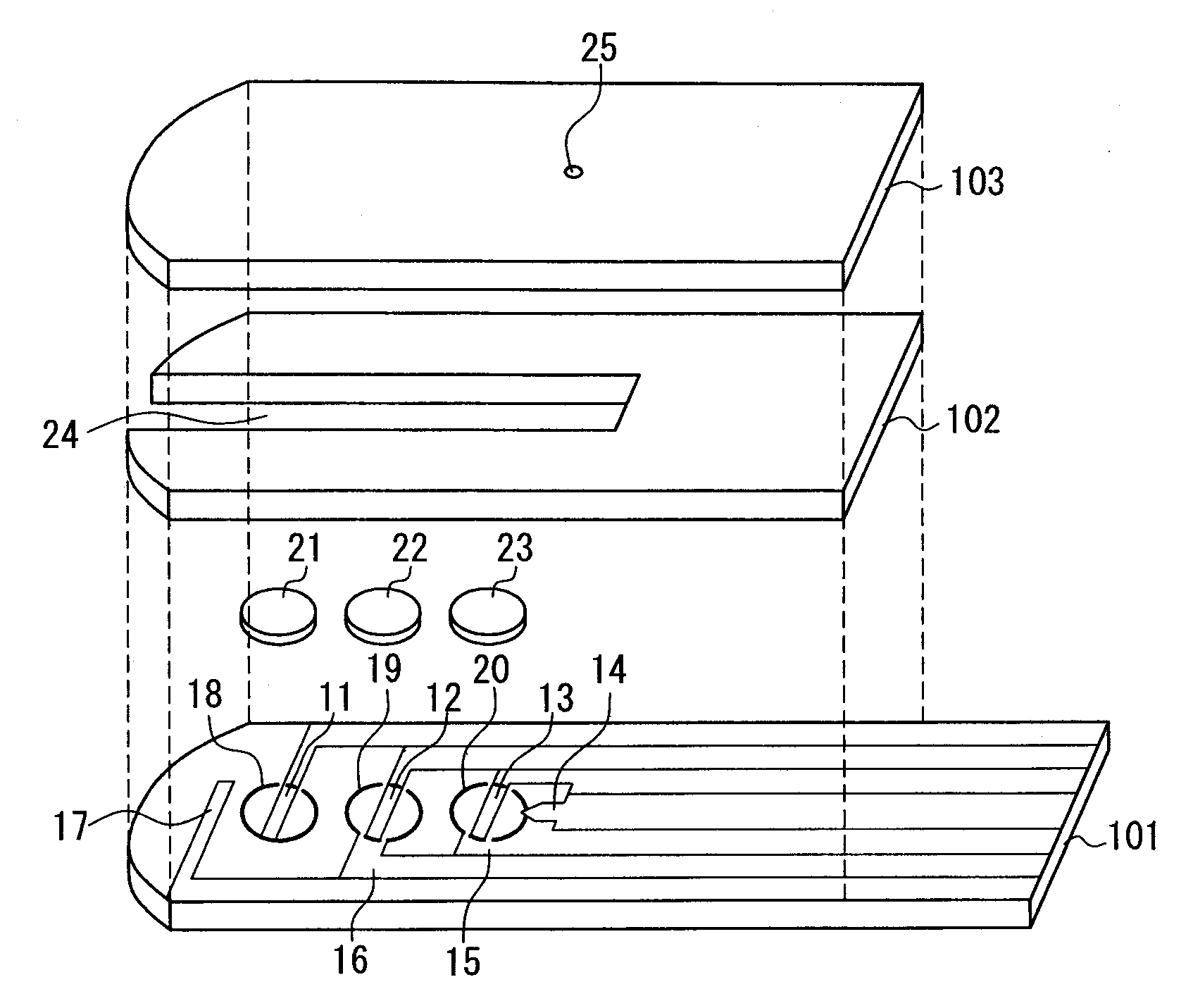
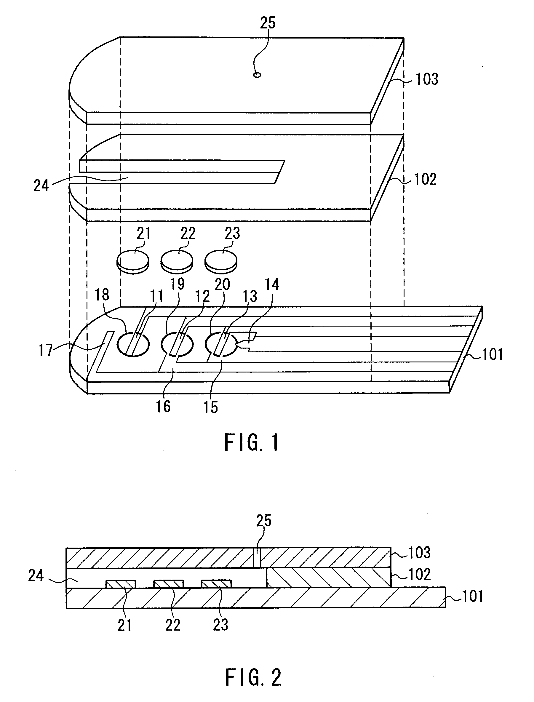
[0063]FIGS. 1, 2, and 3 show one example of a sensor for measuring a blood component according to the present invention. FIG. 1 is an exploded perspective view of the sensor, FIG. 2 is a sectional view of the sensor, and FIG. 3 is a plan view of the sensor. In these three drawings, the same components are given the same reference numerals.

[0064] As shown in the drawings, in this sensor, a first electrode system including a first working electrode 13 and a first counter electrode 15, a second electrode system including a second working electrode 17 and a second counter electrode 11, a third electrode system including a third working electrode 12 and a third counter electrode 16, and a liquid detecting electrode 14 are formed on an insulating substrate 101. A first reagent layer 23 is provided on the first electrode system, a second reagent layer 21 is provided on the second counter electrode 11, and a third reagent layer 22 is provided on the third electrode system. The first reagen...

example 2

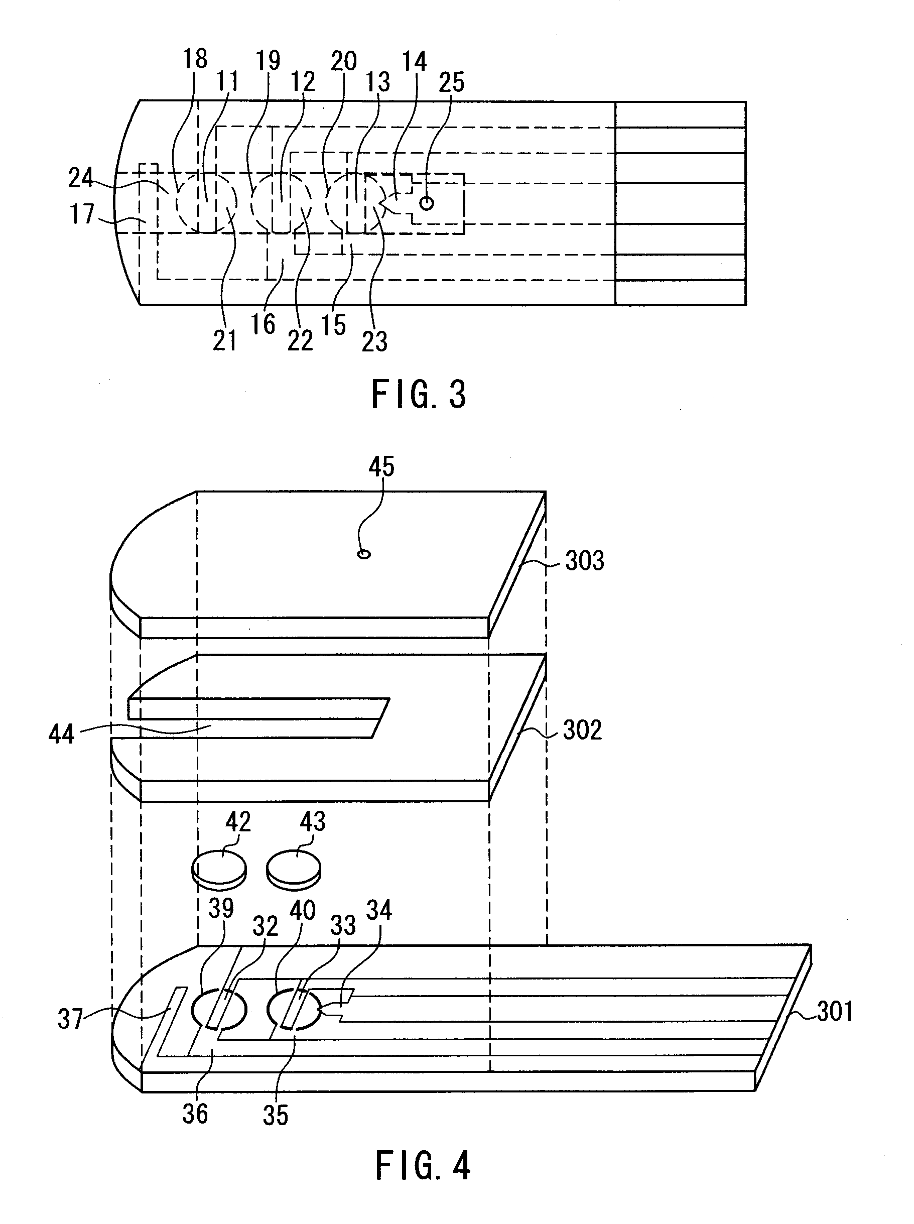
[0084]FIGS. 4, 5, and 6 show another example of a sensor for measuring a blood component according to the present invention. FIG. 4 is an exploded perspective view of the sensor, FIG. 5 is a sectional view of the sensor, and FIG. 6 is a plan view of the sensor. In these three drawings, the same components are given the same reference numerals. In the sensor according to the present example, either one or the combination of the electrodes of the first or third electrode system serves as the counter electrode of the second electrode system of the sensor according to Example 1. Through the shared use of the electrode as described above, it is possible to make the channel for leading blood to the sensor shorter, thereby allowing the amount of blood required as a specimen to be reduced. Moreover, through the shared use of the electrode, the number of the reagent layers can be reduced to two.

[0085] As shown in the drawings, in this sensor, a first electrode system including a first worki...

example 3

[0100]FIG. 7 shows still another example of a sensor for measuring a blood component according to the present invention. FIG. 7 is a plan view showing an electrode pattern in this sensor, which corresponds to the electrode pattern shown in FIG. 6 in which either one or the combination of the electrodes of the first electrode system is shared with the third electrode system as the counter electrode. Except for the above, this sensor has the same configuration as the sensor according to Example 2, and the components, the configuration of the reagent layers, production method, etc. of this sensor are the same as those of the sensor according to Example 2.

[0101] Measurement of a blood glucose level using this sensor can be carried out in the following manner, for example. First, a fingertip or the like is punctured with a dedicated lancet to cause bleeding. On the other hand, the sensor is set in a dedicated measuring device (a meter). The blood supply port of the sensor set in the mea...


PUM

PropertyMeasurementUnit
Electric potential / voltageaaaaaaaaaa
Flow rateaaaaaaaaaa
Currentaaaaaaaaaa

Abstract

The present invention provides a method of measuring a component in blood, by which the amounts of blood cells and an interfering substance can be measured with high accuracy and high reliability and the amount of the component can be corrected accurately based on the amounts of the blood cells and the interfering substance. In a sensor for measuring a blood component, a first working electrode 13 measures a current that flows during a redox reaction of a blood component, a second working electrode 17 measures the amount of blood cells, and a third working electrode 12 measures the amount of an interfering substance. Next, based on the measurement results, the amount of the blood component to be measured is corrected. Thus, more accurate and precise measurement of the amount of the blood component can be realized.

Description

TECHNICAL FIELD [0001] The present invention relates to a method of measuring a blood component and to a biosensor and a measuring device used in the method. BACKGROUND ART [0002] Conventionally, sensors for measuring a blood component have been used for clinical tests, self-measurement of blood glucose level by diabetics, etc. The configuration of the sensor for measuring a blood component is such that, for example, a cover is disposed on an insulating substrate having a working electrode and a counter electrode on its surface with a spacer intervening between the cover and the insulating substrate. On the working electrode and the counter electrode, a reagent containing an oxidoreductase, a mediator (an electron carrier), and the like is provided, thereby forming an analysis portion. The analysis portion communicates with one end of a channel for leading blood to the analysis portion. The other end of the channel is open toward the outside of the sensor so as to serve as a blood s...

Claims


Application Information

Patent Timeline
IPC IPC(8): C12Q1/00G01N33/487G01N27/26G01N27/327G01N27/416
CPCA61B5/14546A61B5/1486G01N27/3277G01N27/3274G01N27/3272G01N33/49A61B5/14G01N27/327G01N27/416C12Q1/004C12Q1/006G01N27/413
Inventor FUJIWARA, MASAKISHINNO, TEPPEIIKEDA, SHIN
Owner PHC HLDG CORP
Learn More