Fast-settling digital automatic gain control

a digital automatic gain control and digital gain control technology, applied in the direction of amplifiers with semiconductor devices/discharge tubes, amplifier control details, differential amplifiers, etc., can solve the problems of high distortion of output, low output value, and low efficiency of receivers and input amplifier circuits

Inactive Publication Date: 2007-06-21
LITE ON TECH CORP
View PDF6 Cites 37 Cited by
  • Summary
  • Abstract
  • Description
  • Claims
  • Application Information

AI Technical Summary

Benefits of technology

[0005] A fast-settling digital automatic gain control circuit/cell comprises first and second gain-controllable amplifiers in series. Each amplifier can be digitally switched between minimum and maximum gains by control logic that receives inputs from a multi-level voltage comparator. A peak detector connected to the output of the first gain-controlled amplifier is used to set the overall operating ranges for several threshold detectors. Four reference voltages are generated from the peak detector. The highest reference voltage is used to clock the gain control logic with a hysteresis comparator to the instantaneous input signal from the first gain-controlled amplifier. The three other lower reference voltages are used with three more hysteresis comparators to provide three-bits o...

Problems solved by technology

Receivers and input amplifier circuits, however, are limited in the ranges of voltages and currents they can process.
So a strong input signal in the first stages of amplification with the gain set too high can result in saturation and clipping, the output will therefore be highly distorted and not very useful.
Too little amplification on a faint signal may...

Method used


Image

  • Fast-settling digital automatic gain control
  • Fast-settling digital automatic gain control
  • Fast-settling digital automatic gain control

Examples


Embodiment Construction

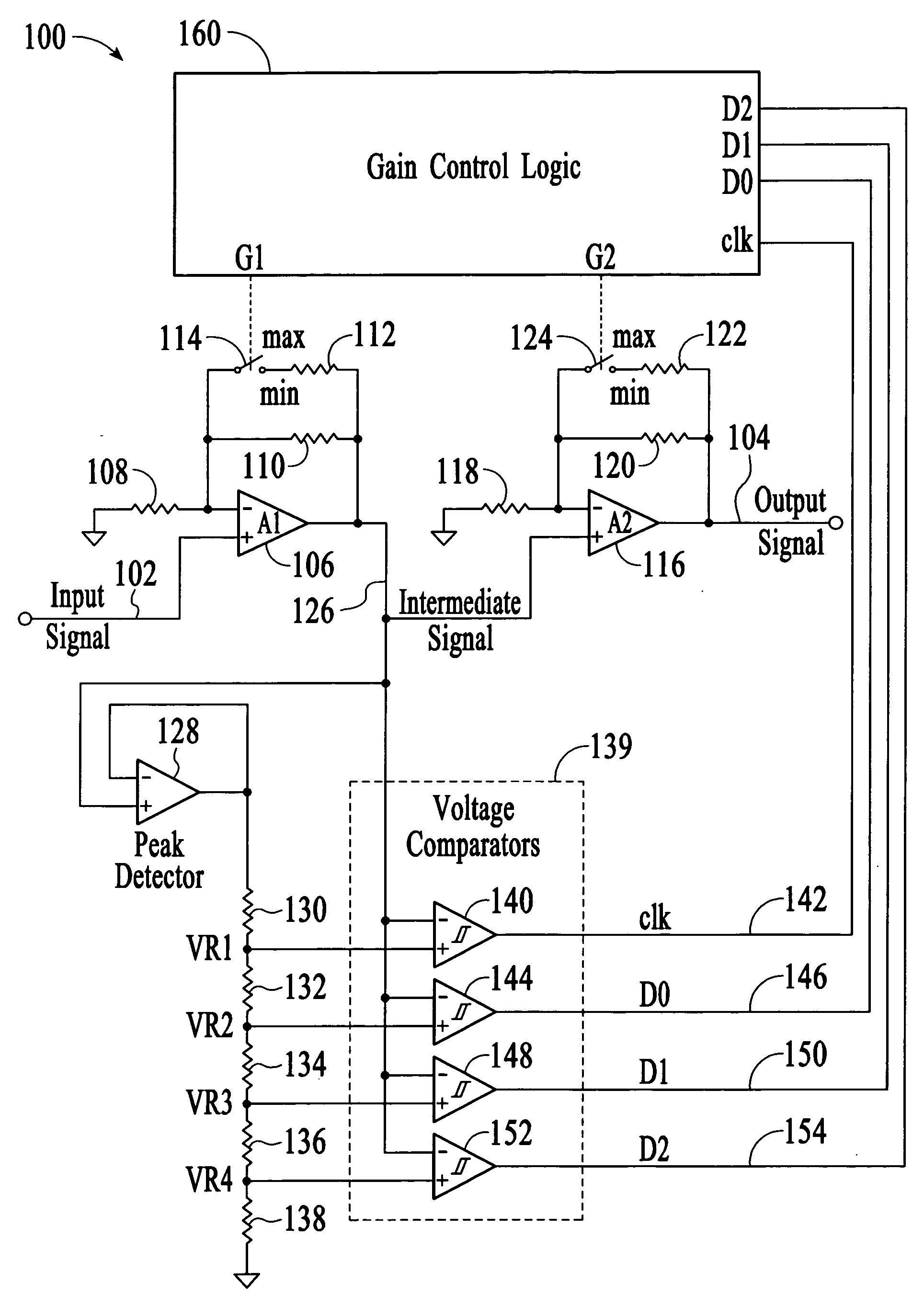
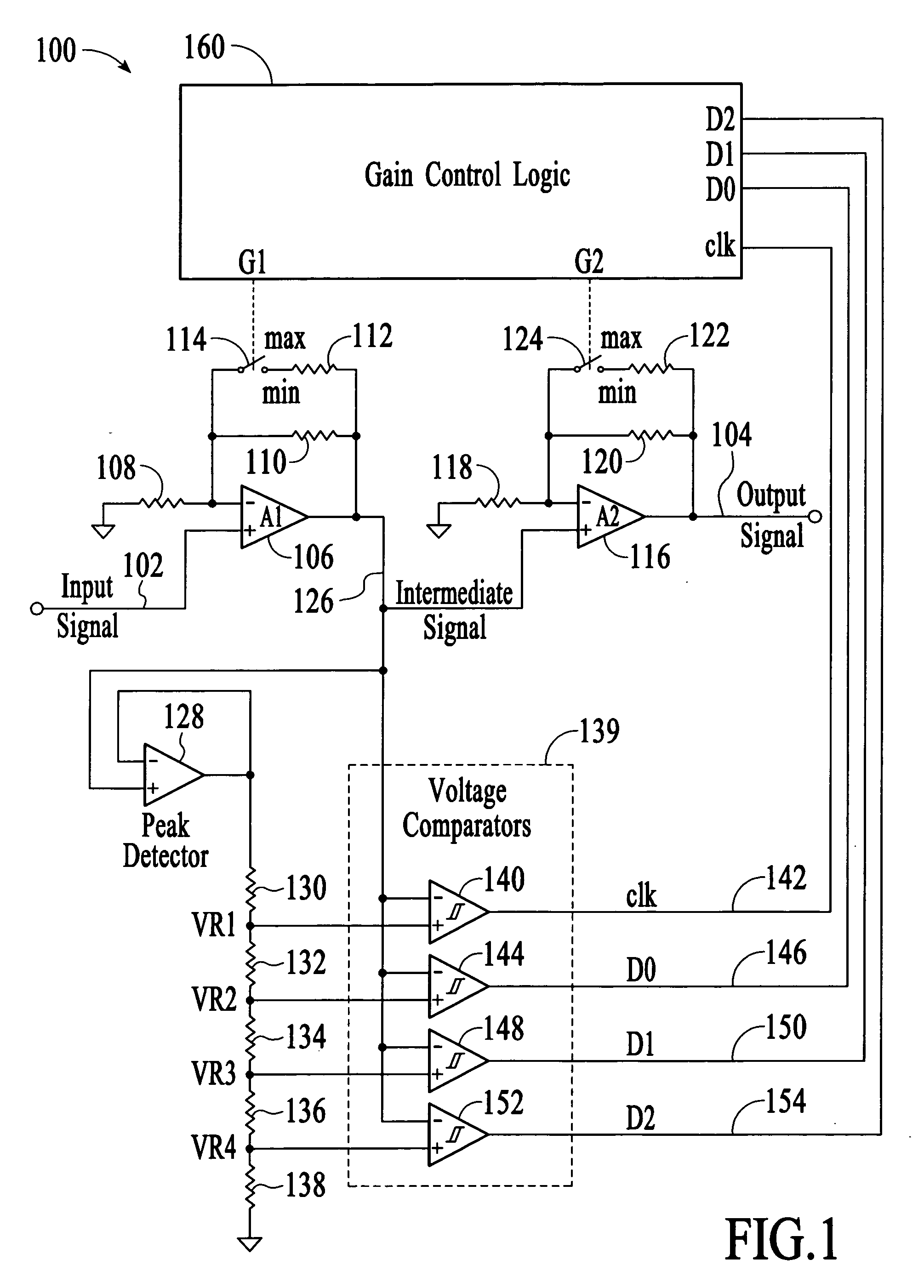
[0014]FIG. 1 represents a fast-settling digital automatic gain control (DAGC) circuit embodiment of the present invention, and is referred to herein by the general reference numeral 100. The DAGC circuit 100 comprises a raw input signal 102 that is AGC-amplified to produce a signal output 104. For example, the circuit 100 can comprise the front-end of an optical fiber channel receiver. Input signal 102 can be the output of a transimpedance amplifier which converted the received photo current from a PIN-photodiode to voltage signal and the output signal 104 can be provided to a quantizer. The DAGC circuit 100 has two stages, the first stage comprises a primary amplifier (A1) 106 that has its inverting input connected to ground by a resistor 108 and a fixed feedback resistor 110. In one example, primary amplifier 106 can be a low-noise transimpedance (TZ) type like an Analog Devices ADN2882.

[0015] The ratio of resistor 110 to resistor 108 determines the maximum gain. Input signal 102...


PUM


Abstract

A fast-settling digital automatic gain control circuit comprises first and second gain-controllable amplifiers in series. Each amplifier can be digitally switched between minimum and maximum gains by control logic that receives inputs from a multi-level voltage comparator. A peak detector connected to the output of the first gain-controlled amplifier is used to set the overall operating ranges for several threshold detectors. Four reference voltages are generated from the peak detector. The highest reference voltage is used to clock and reset the gain control logic with a hysteresis comparator to the instantaneous input signal from the first gain-controlled amplifier. The three other lower reference voltages are used to provide three-bits of digital input data to the gain control logic. Two digital controls are output, a min/max gain bit for the first gain-controlled amplifier, and a similar min/max gain bit for the second gain-controlled amplifier.

Description

BACKGROUND OF THE INVENTION [0001] Analog and video sources can vary widely in the signal amplitudes they produce. Receivers and input amplifier circuits, however, are limited in the ranges of voltages and currents they can process. So a strong input signal in the first stages of amplification with the gain set too high can result in saturation and clipping, the output will therefore be highly distorted and not very useful. Too little amplification on a faint signal may also produce an output that is not useful. [0002] Automatic gain control (AGC) circuits were first widely used in television and radio receivers where the channels being tuned can vary widely in strength. AGC allows the audio volumes and video contrasts to be presented at consistent levels. Audio AGC has also been employed recently to maintain a consistent volume between programs and commercials, and in Internet telephony applications. Originally, purely analog AGC methods were used, but now digital circuits allow th...

Claims


Application Information

Patent Timeline
IPC IPC(8): H03G3/10
CPCH03G1/0088H03G3/001
Inventor TEO, CHEE KEONGXU, LIAN-CHUNYEO, KOK-SOONASUNCION, JOHN JULLUSTAI, WAI KEAT
Owner LITE ON TECH CORP
Why Eureka
Try Eureka