Bandpass sampling receiver and the sampling method

a sampling receiver and bandpass technology, applied in the field of radio signal receivers, can solve the problems of difficult integration with other circuits, increase the cost of receivers, and obstacle to equipment upgrade, and achieve the effects of less cost, easy integration, and easy technical upgrad

Inactive Publication Date: 2007-06-21
KONINKLIJKE PHILIPS ELECTRONICS NV
View PDF1 Cites 51 Cited by
  • Summary
  • Abstract
  • Description
  • Claims
  • Application Information

AI Technical Summary

Benefits of technology

[0010] In the present invention, wideband ADC is required to approach the receiving antenna as near as it can, and AD convert the RF signal directly, then various processing on the received signal should be implemented by programmable DSP (digital signal processing) devices as much as possible. DSP is flexible, costs less and is easy for integration, so this method can realize compatibility of multiple communication protocols and easy for technical upgrade.
[0012] One object of the present invention is to provide a simple bandpass sampling receiver architecture, for AD converting the RF signal directly, without resorting to analog mixers and digital mixers.
[0013] Another object of the present invention is to provide a simple bandpass sampling receiver architecture, for lowering the requirement for ADC performance as much as possible, and offer the method for recovering the orthogonal digital user signals.

Problems solved by technology

But in conventional super heterodyne receiver, IF filter 233 is implemented by bulky and expensive SAW (Surface Acoustic Wave) devices, making it very hard to be integrated with other circuits.
Meanwhile, with the development of multi-mode handsets, the super heterodyne receiver needs a standalone IF SAW filter for every channel bandwidth in every mode, which increases the cost of receivers, and furthermore, the hardware constraints pose an obstacle to the upgrade of equipments.
Moreover, analog mixers are used many times in the receiver, thereby problems like nonlinear effects and image frequency interference, is unavoidable.
In practical systems, such as GSM mobile phone, it's generally very difficult to remove interference completely through RF bandpass filter 220, so the input signal of the sampling circuit often contains wideband interference.
Therefore, the clock signal selected in practical applications often has a frequency much higher than the theoretical value, which often leads to low efficiency.
However, when the sampling frequency is chosen, if N is even, the two paths will get the same result after the signal is sampled, and thus we can't obtain the separated orthogonal user signal s I(t) and Q(t).
Furthermore, the method as how to separate the orthogonal user signals is not disclosed fully in the patent document.
With regard to the above modified receiver architecture, bulky devices such as IF filter, are not used any more, but it s fill fails to depart from the idea that the RF signal is first converted into baseband analog signal and then AD converted.

Method used


Image

  • Bandpass sampling receiver and the sampling method
  • Bandpass sampling receiver and the sampling method
  • Bandpass sampling receiver and the sampling method

Examples


Embodiment Construction

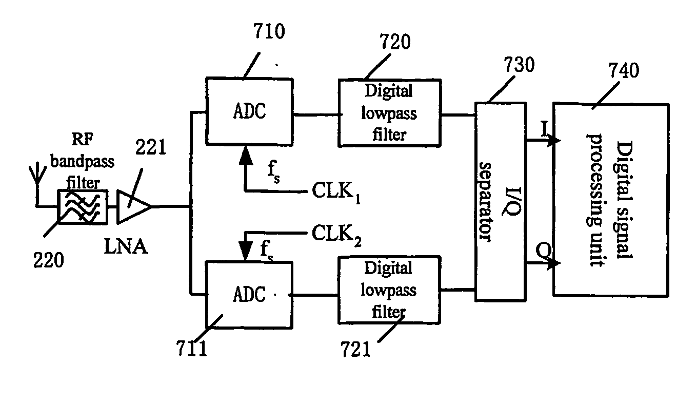
[0024] To clearly describe the features of the present invention, a n analysis will first be given below to the feasible conditions of the two -path sub-sampling receiver architecture in theory, in conjunction with FIG. 5 and FIG. 6, then a detailed description will go to the proposed receiver architecture in an embodiment of the present invention in conjunction with FIG. 7 and provide the method for recovering the user signal.

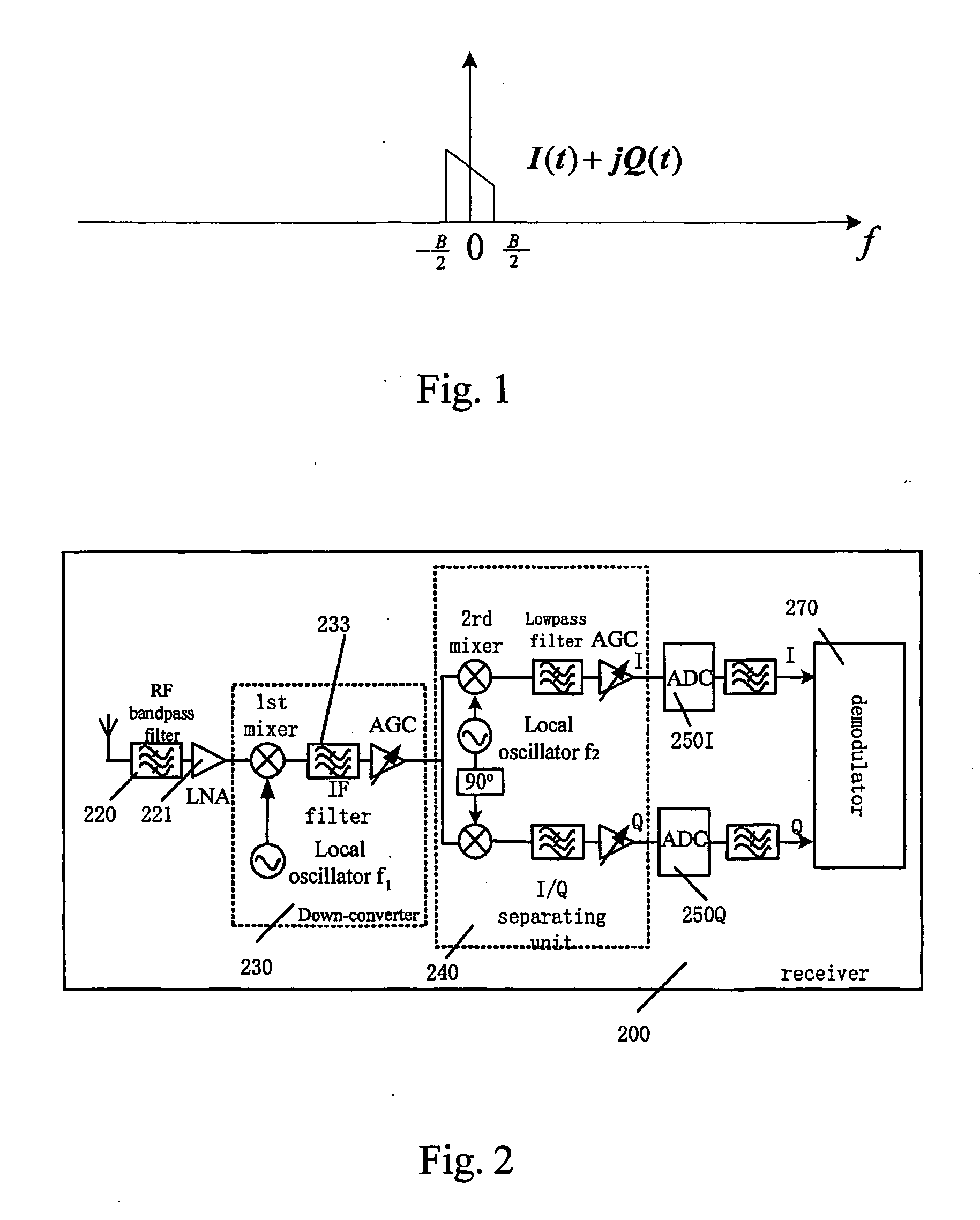
[0025] If the user signal with bandwidth as B shown in FIG. 1 can be expressed by two orthogonal components as I(t)+jQ(t), the RF signal with carrier frequency of fc and quadrature modulated with the user signal can be given by:

S(t)=I(t)cos(ωet+φ)−Q(t)sin(ωct+φ)   (1)

where ωe=2πf is the circular frequency of the carrier, and φ is the initial phase of the carrier.

[0026] For ease to analyze the spectrum characteristic of the RF signal, some necessary mathematical transforms can be made to equation (1), and thus S(t) can be further expressed as two bandpass ...


PUM


Abstract

A bandpass sampling receiver is proposed for receiving RF signals, comprising: the first ADC, for converting the RF signal into the first path of digital signal under the control of the first sampling clock signal; the second ADC, for converting the RF signal into the second path of digital signal under the control of the second sampling clock signal; a signal separating unit, for separating the in-phase signal and the quadrature signal in the first path of digital signal and the second path of digital signal; wherein the frequency of said first sampling clock signal and said second sampling clock signal is l / N of that of said RF signal, and N is a natural number.

Description

FIELD OF THE INVENTION [0001] The present invention relates generally to a radio signal receiver for use in wireless communications, and more particularly, to a radio signal receiver employing bandpass sampling. BACKGROUND ART OF THE INVENTION [0002] In wireless communication, the user signal to be transmitted is usually baseband signal with relatively low frequency and limited bandwidth, and in general can be expressed by two orthogonal components as I(t)+jQ(t). The spectrum can be illustrated as in FIG. 1, where I(t) is the in-phase component and Q(t) is the quadrature component. When the user signal is to be transmitted, the transmitter modulates a carrier signal s, whose frequency is in RF (Radio Frequency) domain, with the user signal and then transmits the RF signal to radio space through the transmitting antenna. [0003] The receiver receives the RF signal from radio space through the antenna, and converts it into baseband digital signal centred at zero frequency so that the w...

Claims


Application Information

Patent Timeline
Patent Type & Authority Applications(United States)
IPC IPC(8): H04L27/22
CPCH04B1/30
Inventor QIAN, XUECHENG
Owner KONINKLIJKE PHILIPS ELECTRONICS NV
Why Eureka
Try Eureka