Reception system with phase alignment of antenna signals

a technology of antenna signals and reception systems, applied in diversity/multi-antenna systems, digital transmission, polarisation/directional diversity, etc., can solve the problems of increasing technical effort and expenditure, and the inability to use ancillary modulation, so as to achieve the effect of improving efficiency

Inactive Publication Date: 2007-06-21
DELPHI DELCO ELECTRONICS EUROPE GMBH
View PDF11 Cites 30 Cited by
  • Summary
  • Abstract
  • Description
  • Claims
  • Application Information

AI Technical Summary

Benefits of technology

[0056] Diversity reception systems for a satellite reception system are known from DE 10206385. There, switching of the antennas is synchronized with the cycle of the data signals, thereby achieving updating of the reference phase at all times. With a reception system which relates to the present invention, these cycle signals are not necessary for controlling the diversity process, something that is advantageous for efficiency.

Problems solved by technology

However, this method has a significant disadvantage in that an additional signal in the form of an ancillary modulation has to be impressed on the signals to be received, to bring about phase alignment.
A disadvantage with this design is the increased technical effort and expenditure, which requires a separate antenna tuner for each antenna.
With mobile reception in a vehicle, a problem of such systems is that when traveling through the Rayleigh reception field, the phase regulation circuit can no longer follow the resulting phase changes for same-phase superimposition of the signals in the summation element, and consequently, the signal of the ancillary modulation, as an undesirable signal in the sum signal, can bring about interference.
In particular, with systems that are sensitive with regard to faithful reproduction of the base band signals in the receiver, ancillary modulation can therefore not be used.

Method used


Image

  • Reception system with phase alignment of antenna signals
  • Reception system with phase alignment of antenna signals
  • Reception system with phase alignment of antenna signals

Examples


Embodiment Construction

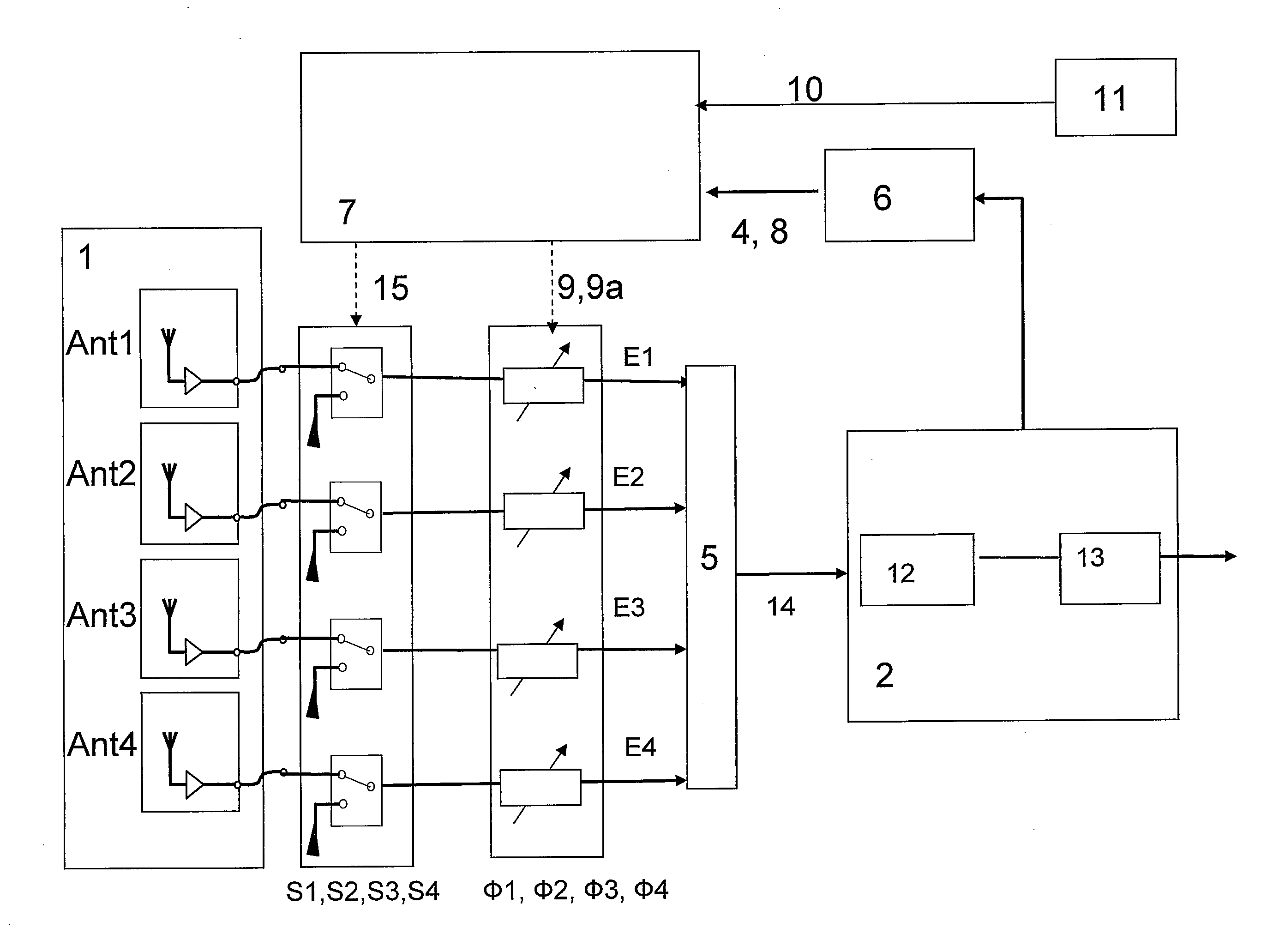
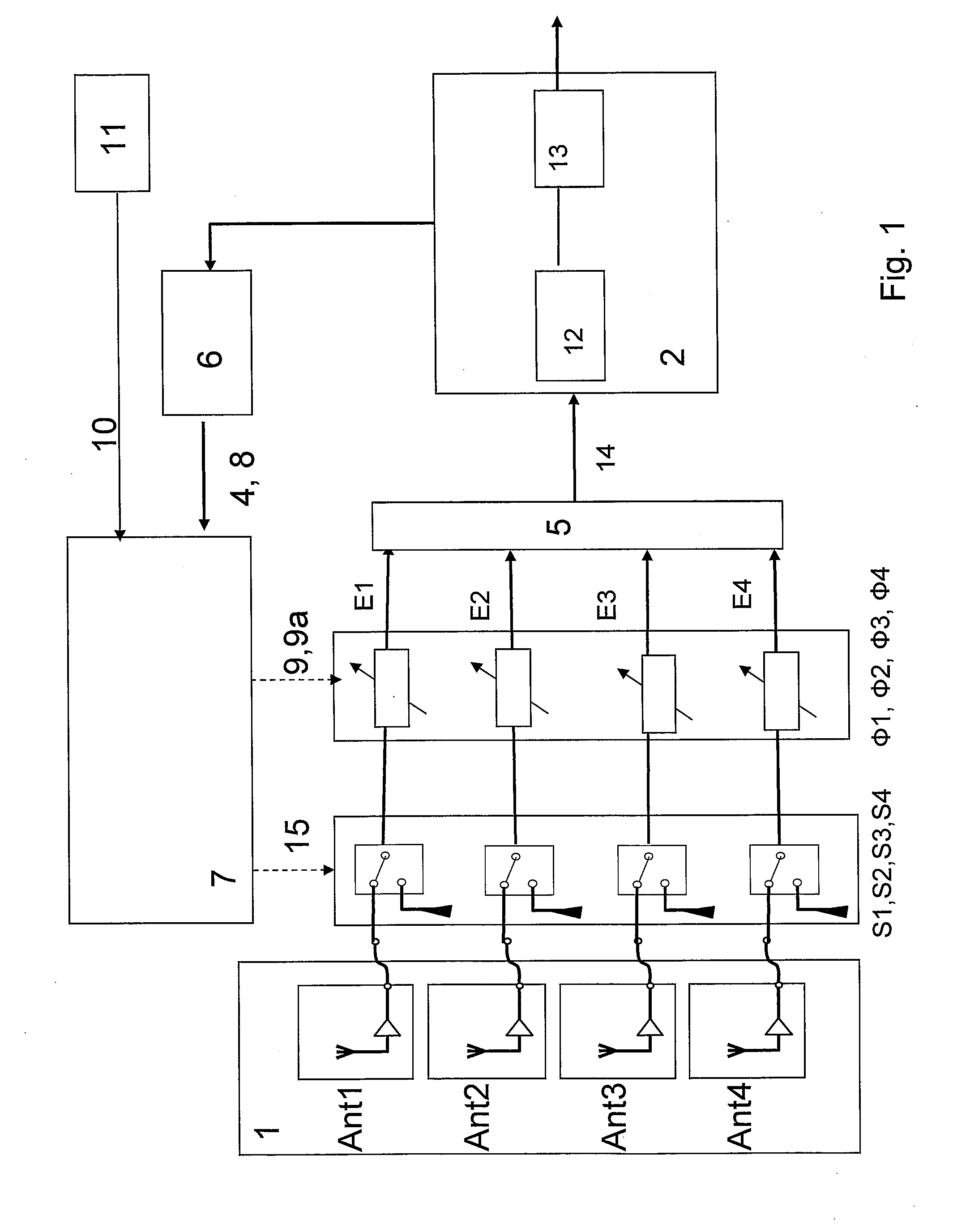
[0088]FIG. 1 shows the reception system according to the invention with a multi-antenna system having antennas Ant1, Ant2, Ant3, Ant4. There are also a plurality of individually adjustable switching elements S1, S2, S3, S4, which can each be connected to associated individually adjustable phase rotation elements Φ1, Φ2, Φ3, Φ4 . . . Φn. There is also a summation or combination circuit 5 for receiving the signals E1, E2, E3, E4, from each of the phase rotation elements. The summation or combination circuit 5 is for combining the reception signals E1, E2, E3, and E4 which are superimposed with the same phase in the summed or combined signal 14. There is a reception circuit 2 which has an input for receiving the combined signal 14. There are also HF-IF parts 12 and 13 disposed inside of the reception circuit 2. The output of this reception circuit 2 feeds into a signal level indicator 6 for displaying the level of the reception signal 14. The output of the level indicator 6 feeds into ...


PUM


Abstract

A reception system for frequency-modulated, i.e. phase-modulated high-frequency signals, for motor vehicles, having a multi-antenna system having at least two antennas, an individually adjustable phase rotation element, situated in the reception path of the corresponding antenna, in each instance, and a subsequent receiver circuit. There is an individually adjustable switching element for switching through or interrupting the signal flow, respectively, is present in the reception path of every antenna. The reception signals are guided by way of phase rotation elements and the adjustable switching elements which are passed to a linear combination circuit, and wherein the combined signal is passed to the receiver circuit. Furthermore, there can be a level indicator for indicating the level of the combined signal in the form of a level signal and a computer device to which this level signal is passed. An the computer device can include an algorithm for determining the phase differences of the reception signals that are present at the input of the combination circuit at a given setting of the phase rotation elements from their level conditions, by means of calculations. This calculation can occur using level measurement samples of the level signal that are performed one after the other, in terms of time, obtained by way of switch setting signals and phase setting signals brought about by the computer device wherein there are differently defined settings of the switching elements or of the phase rotation elements, respectively. Phase setting signals are generated on the basis of the phase differences determined by calculations, for the subsequent setting of the phase rotation elements for phase alignment of the reception signals that are present at the input of the combination circuit when the adjustable switching elements are switched through.

Description

CROSS REFERENCE TO RELATED APPLICATIONS [0001] This application hereby claims priority under 35 U.S.C. 119 from German Patent application DE 10 2005 060 060.3 filed on Dec. 15, 2006. This application also claims priority from 10 2006 057 520.2 filed on Dec. 6, 2006 wherein the disclosures of both of these applications are hereby incorporated herein by reference. [0002] The invention relates to a reception system for high-frequency signals that are modulated in their frequency, i.e. modulated in their phase, for motor vehicles. There can be a device having a multi-antenna system 1 having a plurality of antennas Ant1, Ant2 . . . AN. There can be a switching device S1, S2, . . . S4 for the antenna selection, and an individually adjustable phase rotation element Φ1, Φ2, . . . ΦN, situated in the reception path of the corresponding antenna, in each instance, and a subsequent receiver circuit 2. [0003] Antenna diversity systems of this type are preferably used for ultra-short-wave radio r...

Claims


Application Information

Patent Timeline
Patent Type & Authority Applications(United States)
IPC IPC(8): H04L1/02
CPCH04B7/084H04B7/0874
Inventor LINDENMEIER, STEFANLINDENMEIER, HEINZ
Owner DELPHI DELCO ELECTRONICS EUROPE GMBH
Why Eureka
Try Eureka