Ferrite carrier core material for electrophotography, ferrite carrier for electrophotography and methods for producing them, and electrophotographic developer using the ferrite carrier

a technology of electrophotography and ferrite carrier, which is applied in the direction of developers, instruments, optics, etc., can solve the problems of large residual magnetization and coercive force, scattering of carrier, and liable to generate various image faults, etc., to achieve high magnetization, low resistance, and favorable fluidity

Inactive Publication Date: 2007-06-21
POWDERTECH
View PDF5 Cites 27 Cited by
  • Summary
  • Abstract
  • Description
  • Claims
  • Application Information

AI Technical Summary

Benefits of technology

[0036] The ferrite carrier core material for electrophotography according to the present invention has a homogeneous composition, a certain surface property, a favorable fluidity, a high magnetization and a low resistance. Then, the electrophotographic developer using the ferrite carrier in which the ferrite carrier core material is coated with a resin has a fast charge rising and a stable charge quantity with time. The production method according to the present invention also provides an inexpensive and stable production of the ferrite carrier for electrophotography.

Problems solved by technology

Although the largest effect on the high-quality imaging is to make the carrier of a small particle size, only making the carrier simply of a small particle size reduces the magnetization per carrier particle, and causes the carrier scattering.
Although, as a material for the above carrier, a magnetite or a ferrite having a composition of being very rich in iron is expected from the viewpoint of the targeted magnetization and resistance, a single magnetite has a tendency of having a large residual magnetization and coercive force, and is liable to generate various image faults.
However, by so far proposed methods for producing a ferrite carrier core material, manganese is not sufficiently dispersed, and liable to deviate.
Namely, when β-Fe2O3 used as a common ferrite raw material is used as the main raw material, elements added as by materials other than Fe have a high possibility of deviating, and if made to be of a small particle size, it has a problem of the carrier scattering being liable to occur.
On the other hand, regarding the shape, although it is a well-known fact that spherical ferrite particles are used as a carrier, the true sphere hardly generates friction, and does not have a sufficient charge imparting capability.
Especially since the carrier for full-color image has a high printing rate, if it cannot impart a sufficient friction charge, it may possibly be directly linked with the decrease in the printing quality.
However, when the unevenness is present beyond need, a toner does not only have a possibility of being broken only by stirring a developer in actual machines, but a stress is exerted on a magnet roll driving part because of a poor fluidity of the developer, possibly causing the driving part to be damaged in the worst case.
As a result, in comparison with a carrier core material whose surface does not at all have or slightly has the unevenness, the apparent density does not only becomes low, but the fluidity becomes much worsened, and the charging properties in actual machines are inferior.
Besides, the use as a carrier does not allow a prolonged life because of the brittleness.
Japanese Patent Laid-Open No. 06-483967 and Japanese Patent Laid-Open No. 2000-89518 describe carriers composed of a magnetite and a lithium ferrite for which the grain size (sintered primary particle) is defined, and the objects are to prevent the exfoliation of the resin-coated layer and to sharply maintain the charge distribution of the toner under high temperature and high humidity conditions, but they cannot be said to be sufficient from the viewpoint of the objects to achieve the improvement in the developer fluidity in actual machines and the charging stability of the carrier with time.
Conventional small particle size carrier core materials have a large problem also with the classifying precision on production, and are known to rapidly worsen in yield with the smaller particle size.
Besides, due to large raw material particles, they have a problem that elements hardly melt and diffuse and easily deviate.
Moreover, the variation in the surface property possibly due to the element deviation is remarkably developed, adversely affecting not only characteristics of the carrier core materials such as the fluidity, density and apparent density, but the process yield including classification precision.
However, with the increased sintering temperature, the generation of the unevenness on the carrier core material surface becomes difficult.
With the temperature lower than that, a carrier core material whose magnetization is high, whose resistance is low, and whose surface has unevenness cannot be fabricated because of too much reduced magnetization.
However, it uses too large raw material particles, and is a producing method insufficient to obtain a carrier core material having the surface property and homogeneity of elements as is described later in the present invention.

Method used


Image

  • Ferrite carrier core material for electrophotography, ferrite carrier for electrophotography and methods for producing them, and electrophotographic developer using the ferrite carrier
  • Ferrite carrier core material for electrophotography, ferrite carrier for electrophotography and methods for producing them, and electrophotographic developer using the ferrite carrier
  • Ferrite carrier core material for electrophotography, ferrite carrier for electrophotography and methods for producing them, and electrophotographic developer using the ferrite carrier

Examples


example 1

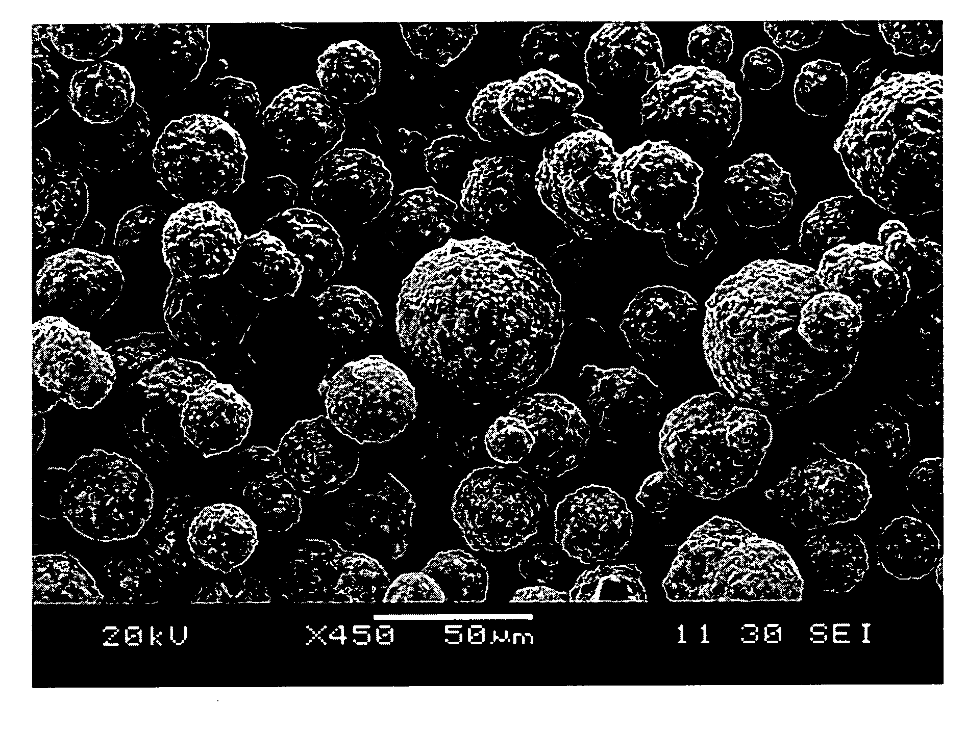
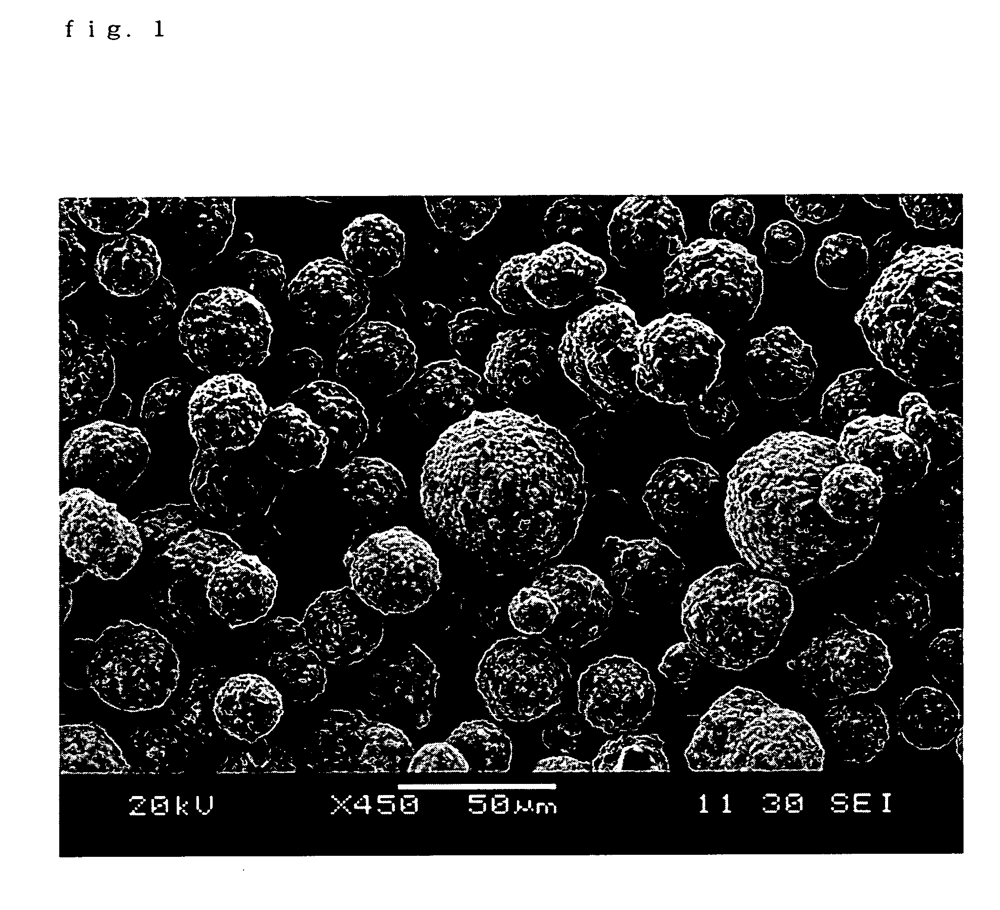
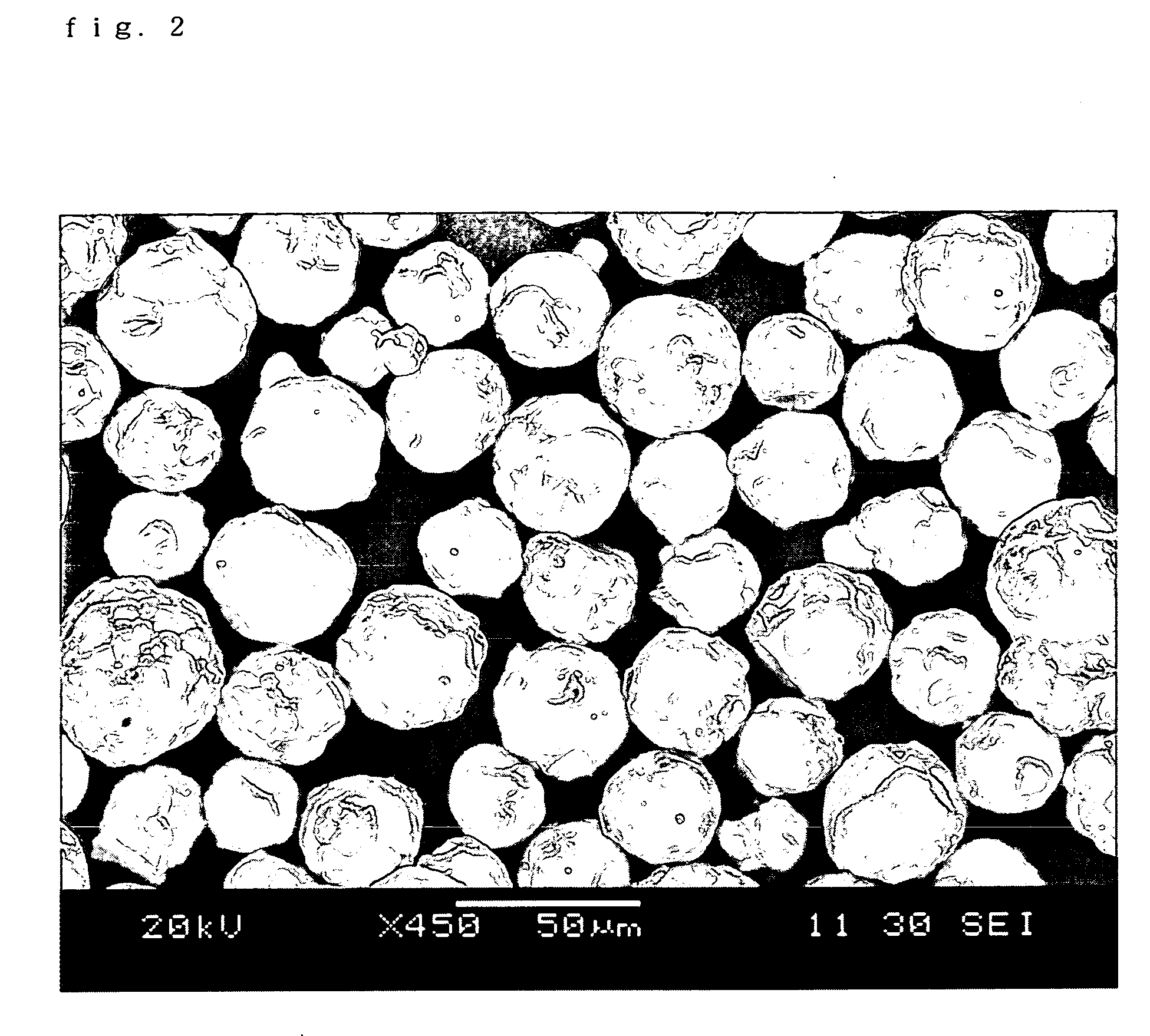
(Production of an Fe—Mn Composite Oxide)

[0093] FeSO4 and MnSO4 were dissolved in warm water of 60° C. in a molar ratio of Fe2+:Mn2+=8:1 (solution A).

[0094] NaOH of an amount to completely neutralize the FeSO4 and MnSO4 was dissolved in water (solution B).

[0095] Fe2+ and Mn were converted into Fe3O4 and MnFe2O4 , whose weights were calculated from the numbers of total moles of Fe2+ and Mn present in the solution A, and tartalic acid of 1 wt. % to the total weight was dissolved in warm water, then added to the solution B, and raised to a temperature of 90° C. (solution C).

[0096] With the temperature kept at 90° C., the solution A was added to the solution C under stirring (slurry D). The pH of the slurry D containing Fe(OH)2 and Mn(OH)2 was made to be 10.5 by addition of NaOH, and the slurry D was oxidized by dispersing the compressed air in the slurry till Fe2+ and Fe(OH)2 became absent. The confirmation of weather or not Fe2+ and Fe(OH)2 became absent was judged by the titratio...

example 2

[0100] Carrier core material particles were obtained as in Example 1, but with spherical manganese ferrite carrier core particles having an average particle size of 20 μm obtained by crushing and classifying the same sintered substance as that obtained in Example 1.

example 3

[0101] Particles before sintering were made by a spray drier to be of an average particle size of 103 μm, and sintered in an atmosphere controllable electric furnace (sintering temperature of 1,250° C., oxygen concentration of 0 vol %) to obtain a manganese ferrite sintered substance. The sintered substance was crushed and classified to obtain spherical manganese ferrite carrier core material particles having an average particle size of 80 μm.


PUM


Abstract

A ferrite carrier core material for electrophotography having a homogeneous composition, a certain surface property, a favorable fluidity, a high magnetization and a low resistance, and a ferrite carrier for electrophotography methods for producing them, and an electrophotographic developer using the ferrite carrier-core material, which exhibits a fast charge rising and a stable charge quantity with time, are provided. A ferrite carrier core material for electrophotography whose surface is divided by grooves or streaks into 2 to 50 regions per 10 μm and which has a manganese ferrite as a main component, and a method for producing the ferrite carrier core material for electrophotography using an Fe—Mn composite oxide as the raw material, and a method for producing a ferrite carrier for electrophotography are employed.

Description

BACKGROUND OF THE INVENTION [0001] 1. Field of the Invention [0002] The present invention relates to a ferrite carrier core material for electrophotography which has a high magnetization, a low resistance, a homogeneous composition, a certain surface property, and a favorable fluidity, a ferrite carrier for electrophotography, methods for producing them, and an electrophotographic developer using the ferrite carrier. [0003] 2. Description of the Related Art [0004] The two-component developer used in electrophotography is constituted of a toner and a carrier, and the carrier is a carrier material which is mixed and stirred with the toner in a development box, gives a desired charge to the toner, carries the charged toner to an electrostatic latent image on a photoreceptor, and forms a toner image. The carrier is, after having formed the toner image, held by a magnet and stays on a magnet roll, is returned again to the development box, again mixed and stirred with new toner particles,...

Claims


Application Information

Patent Timeline
Patent Type & Authority Applications(United States)
IPC IPC(8): G03G9/113
CPCG03G9/107G03G9/1075G03G9/1136G03G9/1139G03G9/1085
Inventor AGA, KOJINAITO, TAKESHIIGARASHI, TETSUYAHONJO, TOSHIO
Owner POWDERTECH
Why Eureka
Try Eureka