Turbocharger system

a technology of turbocharger and engine, which is applied in the direction of machines/engines, output power, electric control, etc., can solve the problems of inefficient and/or undesirable operation of the combustion engine, unacceptably high exhaust emission level of combustion, and sudden large load placed on the power generation system

Inactive Publication Date: 2007-06-28
CATERPILLAR INC
View PDF90 Cites 44 Cited by
  • Summary
  • Abstract
  • Description
  • Claims
  • Application Information

AI Technical Summary

Problems solved by technology

For example, in a power generation system used to provide electric energy for a building, if a sudden large increase in demand for electric energy occurs due, for example, to activation of one or more appliances requiring a substantial amount of electricity, a sudden large load will be placed on the power generation system.
Such sudden large loads may cause the engine speed of the combustion engine to drop to an undesirably low speed (sometimes referred to as an “under-speed condition”), which may result in inefficient and / or undesirable operation of the combustion engine.
In combination with the reduced engine speed that accompanies the sudden load, however, the resulting combustion may exhibit unacceptably high exhaust emission levels due to an overly rich air-to-fuel ratio (AFR).
If, however, the amount of fuel delivered to the engine is not also increased, an acceptable AFR will not likely be achieved, and there will not be a sufficient increase in torque to counteract the sudden load on the power generation system.
Due to its exhaust gas-driven nature, however, a turbocharger may take an undesirably long time to respond to the need for increased output torque in response to a sudden change in load.
In particular, since the turbocharger's compressor relies on the exhaust gas for driving its turbine, at low engine speeds that may occur as a result of a sudden load increase, the turbocharger's ability to provide a responsive increase in intake pressure may be undesirably slow.
For power generation systems that experience sudden loads, however, detecting a motor's rotational speed and an accelerator pedal depression may not provide an effective determination basis and / or a quick enough response for increasing the rotation of the turbocharger's compressor in order to provide an increase in a combustion engine's torque output.
Not only may the device of the '530 patent not provide an effective determination basis and / or a quick enough response for increasing the rotation of the turbocharger's compressor in order to provide an increase in a combustion engine's torque output, but also, the device of the '530 patent does not recognize the energy recovery capabilities, overall efficiency, and increased engine flexibility that may be achieved by employing additional features such as Miller Cycle operation, multiple stage pressurization of intake air, and variable valve timing, for example.
While the disclosure of the Lieberherr patent recognizes a number of important expedients, such as, dual stage turbocharging, late intake valve closing to maintain the intake valve open for a portion of the compression stroke to yield a reduced effective compression ratio at high engine loads, and variable valve timing, Leiberherr does not recognize the advantages of a turbocharger controller employed in connection with an electric machine operably coupled to the turbocharger.
While the disclosure of the Miller patent (U.S. Pat. No. 2,670,595) recognizes a number of important expedients, such as, pressurizing and cooling the intake air, variable intake valve timing, and both very early intake valve closing and late intake valve closing to vary the effective compression ratio in consonance with load, the Miller patent does not recognize the advantages of a turbocharger controller employed in connection with an electric machine operably coupled to the turbocharger.
While the Miller '934 patent recognizes a number of important expedients, such as, pressurizing and cooling the intake air, variable valve timing, and maintaining the intake valve open during a majority portion of the compression stroke to as much as 60 or 70 degrees before top dead center in the compression stroke, the Miller '934 patent does not recognize the advantages of a turbocharger controller employed in connection with an electric machine operably coupled to the turbocharger.

Method used


Image

  • Turbocharger system
  • Turbocharger system
  • Turbocharger system

Examples


Embodiment Construction

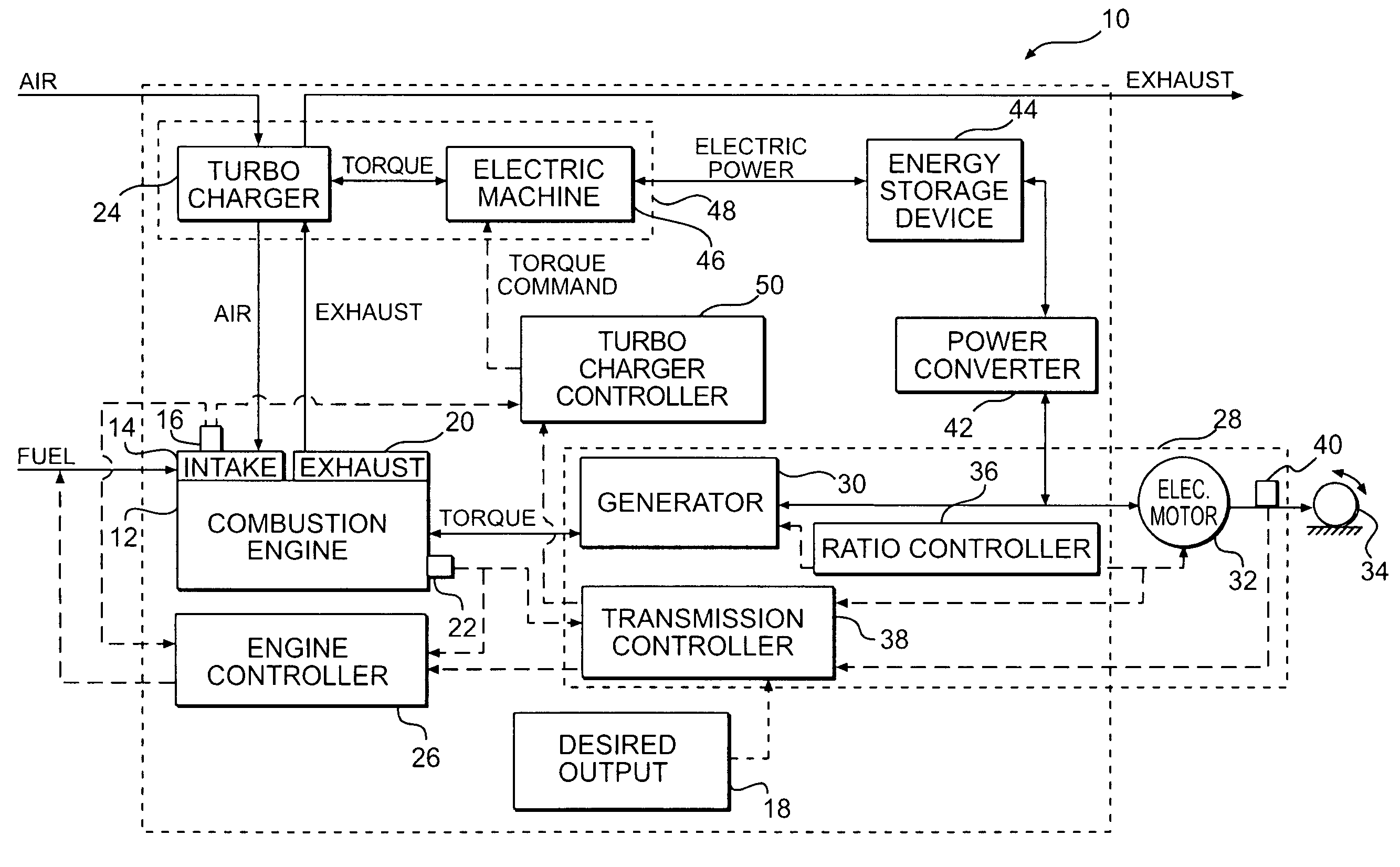
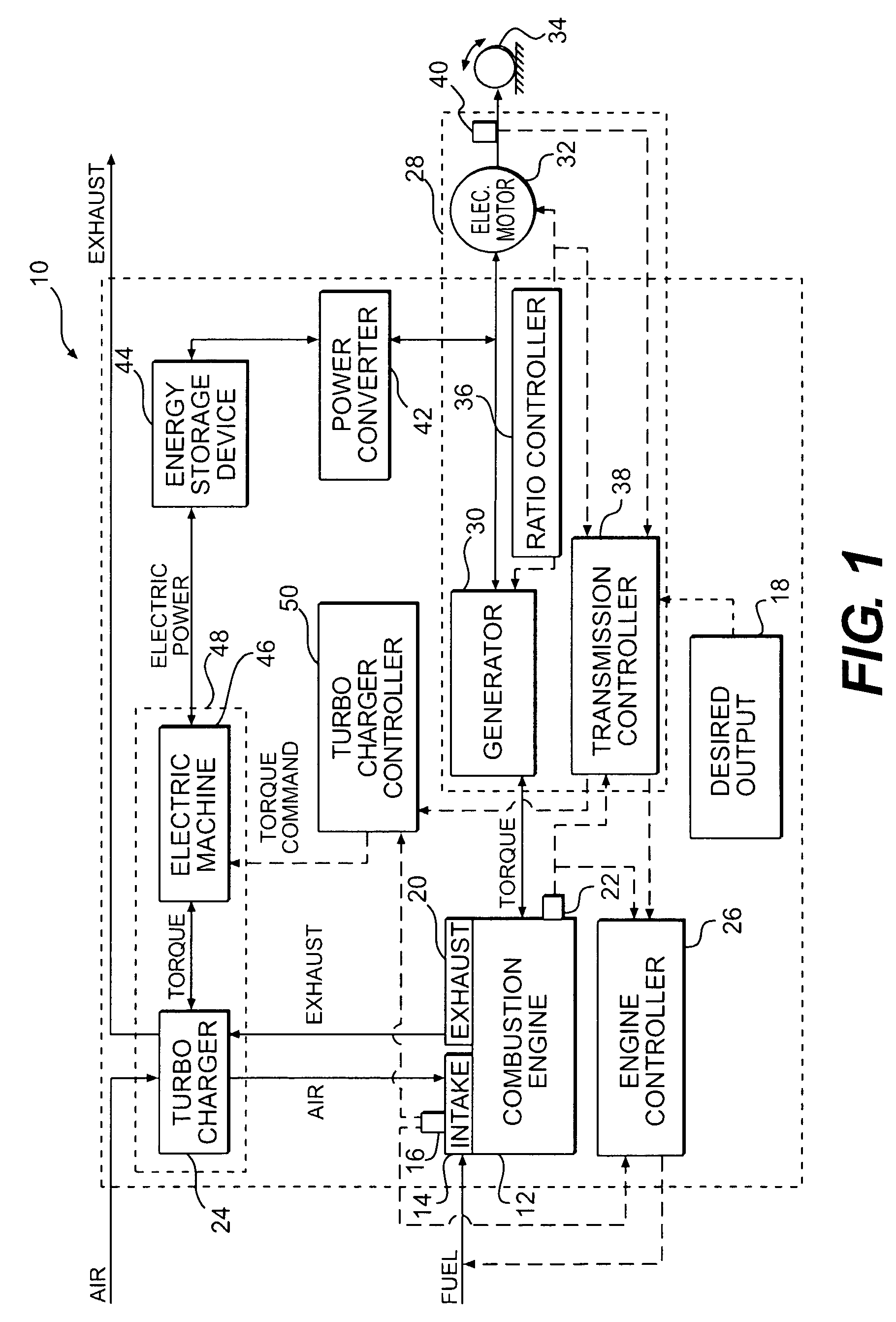
[0026]FIG. 1 schematically illustrates an exemplary power generation system 10, for example, an electric power generation system. Power generation system 10 may include one or more combustion engines 12 configured to generate mechanical energy. For example, combustion engine 12 may be an internal combustion engine configured to accept air and fuel via an intake system 14 including an intake manifold and to convert a mixture of the air and fuel into mechanical energy via combustion. Intake system 14 may include a pressure sensor 16 configured to emit a pressure signal representing the magnitude of pressure in the intake manifold. The mixture of air and fuel may be controlled such that its air-to-fuel ratio (AFR) is optimum for desired operation to, for example, improve fuel efficiency and / or reduce exhaust emissions. Further, the amount of air and / or fuel delivered to combustion engine 12 may be at least partially controlled via a signal indicative of a desired output 18, which may b...


PUM


Abstract

A system for controlling intake pressure of a combustion engine operably coupled to a power generation system includes at least one turbocharger operably coupled to the intake system of the combustion engine. The at least one turbocharger is configured to increase the intake pressure in the intake system of the combustion engine. A turbocharger controller is configured to compare actual and desired intake pressures and control operation of the at least one turbocharger based on the comparison such that the turbocharger supplies a desired intake pressure to the combustion engine.

Description

[0001] This application is a continuation-in-part of U.S. patent application Ser. No. 11 / 396,560, filed Apr. 4, 2006, which is a continuation of U.S. patent application Ser. No. 11 / 094,276, filed Mar. 31, 2005, now U.S. Pat. No. 7,076,954. The entire contents of application Ser. No. 11 / 396,560 and U.S. Pat. No. 7,076,954 are incorporated herein by reference.TECHNICAL FIELD [0002] The present disclosure relates generally to a turbocharger system and, more particularly, to an electric turbocharger system for use with a power generation system. BACKGROUND [0003] A power generation system may used to generate power for either a stationary or a vehicular application. For example, an electric power generation system may used to provide electric power for a building or to provide power for propelling a vehicle and / or operating systems of a vehicle that require electric energy. In particular, a power generation system may be used to provide electric energy for what is sometimes referred to ...

Claims


Application Information

Patent Timeline
Patent Type & Authority Applications(United States)
IPC IPC(8): F02D23/00F02B33/44
CPCF02B29/0412F02B39/10F02B2275/14F02D13/0226F02D13/0269F02D15/04F02D23/02F02D41/0007F02D2200/0406F02M25/0711F02M25/0727Y02T10/144Y02T10/142F02M26/08F02M26/23Y02T10/12
Inventor SOPKO, THOMAS MICHAEL JR.VANDERHAM, MICHAELCASEY, KENT ALLENKURAS, BRIAN D.
Owner CATERPILLAR INC
Why Eureka
Try Eureka