Air conditioning systems for vehicles

a technology for air conditioning systems and vehicles, applied in the direction of subcoolers, lighting and heating apparatus, transportation and packaging, etc., can solve the problems of reducing the energy efficiency of carbon dioxide as a refrigerant, reducing and reducing the pressure so as to improve the energy efficiency of a natural refrigerant and reduce the effect of radiated natural refrigerant pressur

Inactive Publication Date: 2007-06-28
SANDEN CORP
View PDF6 Cites 12 Cited by
  • Summary
  • Abstract
  • Description
  • Claims
  • Application Information

AI Technical Summary

Benefits of technology

[0008] According to an embodiment of the invention, air conditioning systems for vehicles may comprise a first refrigeration cycle, an expander, and a second refrigeration cycle. The first refrigeration cycle may comprise a first compressor for compressing refrigerant, a first radiator fluidly connected to the compressor and configured to radiate heat from the refrigerant, a pressure reduction mechanism configured to reduce a pressure of refrigerant from the first radiator; an evaporator configured to evaporate an amount of refrigerant, and a gas / liquid separator configured to separate evaporated refrigerant from refrigerant in a liquid state. The expander may be disposed on a first fluid communication path between an outlet of the first radiator and an inlet of the first pressure reduction mechanism. The second refrigeration cycle, which may be a cascade cycle relative to the first refrigeration cycle, may comprise a second compressor powered by a pressure reduction and expansion energy of refrigerant resulting from an adiabatic expansion of the refrigerant carried out by the expander.
[0009] According to another embodiment of the invention, a method is provided for improving the energy efficiency of a natural refrigerant utilized in a vehicle air conditioner. The method may comprise the steps of performing a first refrigeration cycle and of performing a second refrigeration cycle. The first refrigeration cycle may comprise the substeps of compressing a first, natural refrigerant, radiating heat from the compressed natural refrigerant, expanding the compressed natural refrigerant, harnessing energy resulting from the expansion of the natural refrigerant, reducing a pressure of the radiated, compressed natural refrigerant; evaporating an amount of natural refrigerant, and separating evaporated refrigerant from refrigerant in a liquid state. The second refrigeration cycle, which may be a cascade cycle relative to the first refrigeration cycle, may comprise the substep of compressing a second refrigerant using energy harnessed from the expansion of the natural refrigerant.

Problems solved by technology

Use of freon-based refrigerants in air conditioning systems for vehicles has been restricted due to environmental concerns.
Carbon dioxide refrigerant is non-toxic and non-combustible, but the temperature of refrigerant discharged from a compressor is relatively high, and the theoretical energy efficiency of carbon dioxide as a refrigerant is relatively low.
), which may occur frequently when air conditioning is desired, during an idling operation, a thermal load on a refrigeration cycle, in particular, a radiator (e.g, a gas cooler) thereof, increases, and a temperature of refrigerant at a suction side of a compressor rises, which may result in superheating of the refrigerant.
In such a condition, the heat radiation ability of an internal heat exchanger is reduced, and it may become difficult to lower the temperature of refrigerant at the exit side of the radiator sufficient for adequate air conditioning or cooling effect.

Method used


Image

  • Air conditioning systems for vehicles
  • Air conditioning systems for vehicles
  • Air conditioning systems for vehicles

Examples


Embodiment Construction

[0016] Preferred embodiments of the present invention, and their features and advantages, may be understood by referring to FIGS. 1-4B, like numerals being used for corresponding parts in the various drawings.

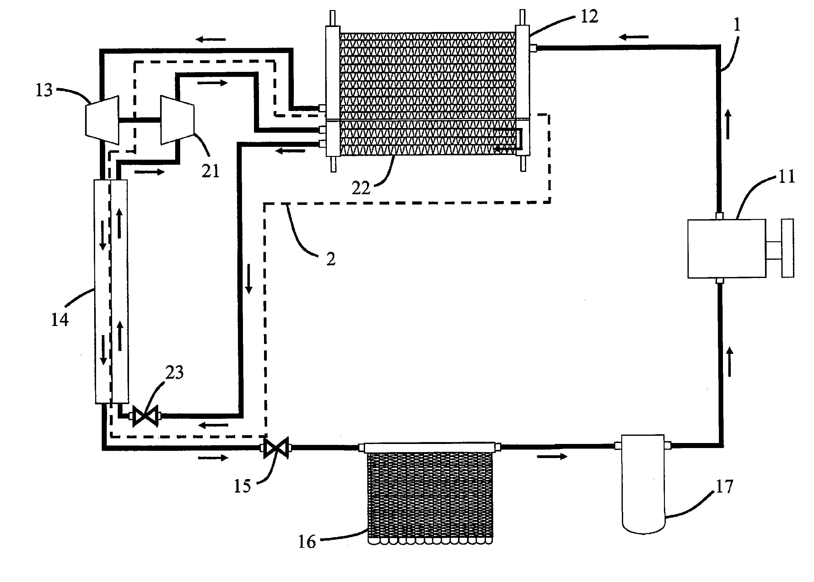
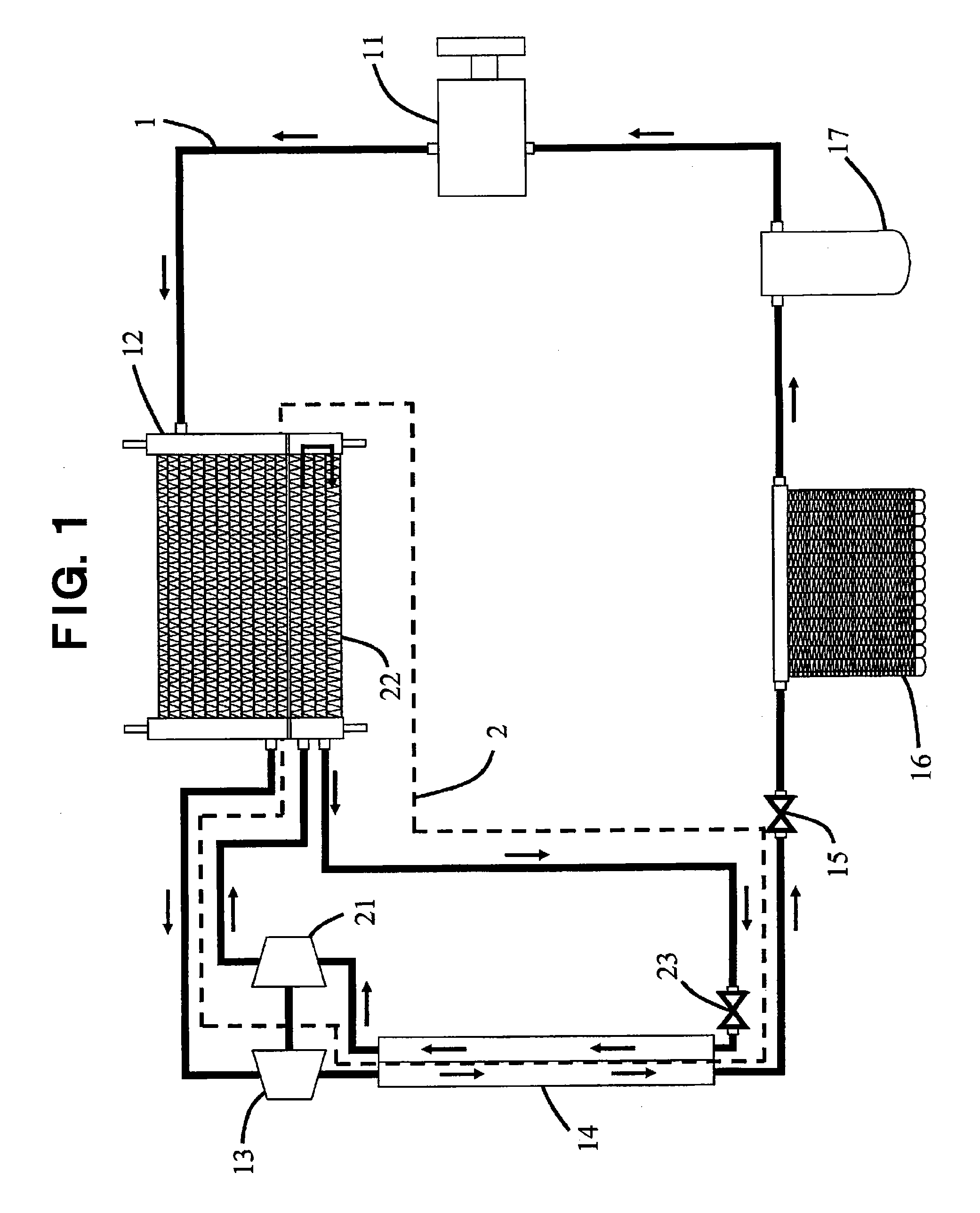
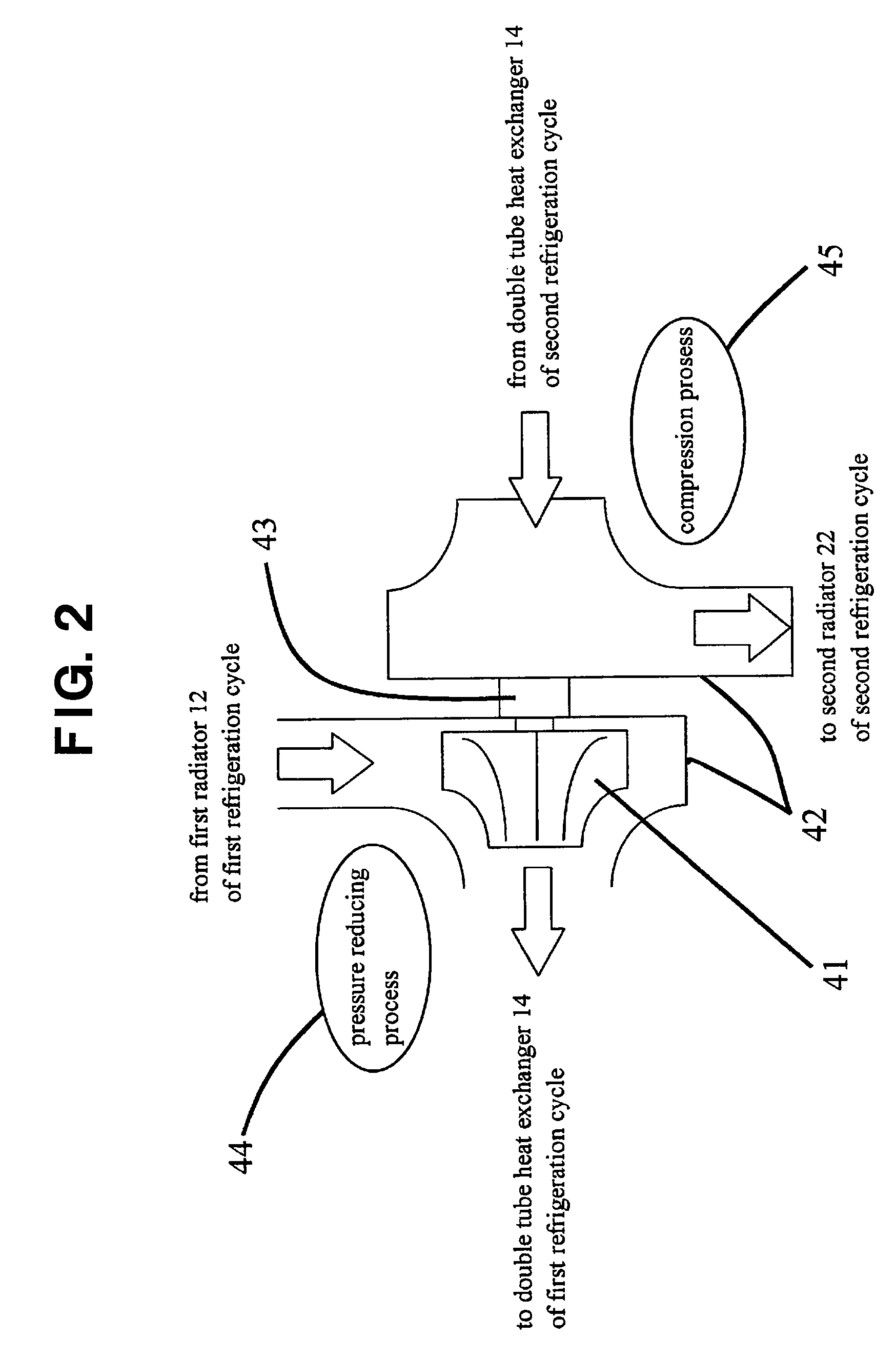
[0017] Referring to FIG. 1, a refrigeration cycle 1 may be a refrigeration cycle for cooling an interior of a vehicle. In this first refrigeration cycle 1, a first compressor 11 for compressing refrigerant and a first radiator 12, which may be a gas cooler, for radiating heat from refrigerant may be provided. An expander 13 for reducing a pressure of and expanding refrigerant volume may be provided at a downstream position of first radiator 12 in the refrigerant flow direction. Expander 13 may be configured to harness energy resulting from the pressure reduction and expansion part of a pressure reducing process for refrigerant, which may be due to adiabatic expansion at expander 13 that is isoentropic, thereby permitting harnessing of the resultant energy. Generally, using a k...


PUM


Abstract

An air conditioning system for a vehicle includes a first refrigeration cycle, an expander, and a second refrigeration cycle. The first refrigeration cycle includes a first compressor, a first radiator, a first pressure reducer, an evaporator, and a gas/liquid separator. The expander is disposed on a first fluid communication path between the first radiator and the first pressure reducer. The second refrigeration cycle, which is provided as a cascade cycle, includes a second compressor powered by energy harnessed from adiabatic expansion of the refrigerant at the expander, thereby obviating the need for an additional power source for the second refrigeration cycle. A heat exchanger further is provided on a second fluid communication path in the second refrigeration cycle. The heat exchanger is configured to provide a heat exchange between refrigerant disposed within each of the respective first and second fluid communication paths.

Description

CROSS-REFERENCE TO RELATED APPLICATION [0001] This application claims priority to and the benefit of Japanese Patent Application No. 2005-377877 filed on Dec. 28, 2005, the disclosure of which is incorporated herein by reference. BACKGROUND OF THE INVENTION [0002] 1. Field of the Invention [0003] The present invention relates to air conditioning systems for vehicles, and specifically, to air conditioning systems for vehicles using a natural refrigerant, such as carbon dioxide. [0004] 2. Description of Related Art [0005] Use of freon-based refrigerants in air conditioning systems for vehicles has been restricted due to environmental concerns. As a result, natural refrigerants, such as carbon dioxide, are being used as a replacement for freon-based refrigerants. Carbon dioxide refrigerant is non-toxic and non-combustible, but the temperature of refrigerant discharged from a compressor is relatively high, and the theoretical energy efficiency of carbon dioxide as a refrigerant is relat...

Claims


Application Information

Patent Timeline
Patent Type & Authority Applications(United States)
IPC IPC(8): B60H1/32F25B7/00F25B1/00
CPCB60H1/323B60H2001/3295B60H2001/3297F25B7/00F25B9/008F25B9/06F25B40/02F25B2309/061
Inventor MATSUMOTO, YUUICHITSUBOI, MASATOSUZUKI, KENICHI
Owner SANDEN CORP
Why Eureka
Try Eureka