
Liquid surface detection device

Inactive Publication Date: 2007-06-28
FUJIFILM CORP +1
View PDF1 Cites 50 Cited by
  • Summary
  • Abstract
  • Description
  • Claims
  • Application Information

AI Technical Summary

Benefits of technology

[0005] In view of the foregoing, a primary object of the present invention is to provide a liquid surface detection device that can improve the detection sensitivity while preventing occurrence of errors due to external noises.
[0009] Because of the filtering circuits, the influence of noises on the signals is suppressed, and the detection sensitivity is improved by raising the amplification rates of the filtering circuits without increasing the risk of detection errors.
[0010] Setting the frequency of the oscillator not less than 50 times the frequency of the capacitance index signal permits amplifying only one frequency component separately from the other, so it becomes possible to detect the liquid surface at a high accuracy while suppressing detection errors, even while there is a noise tuned in to a power source frequency or a high frequency noise. Setting the frequency of the oscillator at 100 kHz to 2000 kHz suppresses occurrence of electromagnetic interference waves. Moreover, setting the frequency of the oscillator at least 400 kHz makes the liquid surface detection device more protective against noises caused by ultrasonic equipments.

Problems solved by technology

If the tip of the suction probe is put deeply into the liquid to suck, the amount of the liquid adhering to the periphery of the probe becomes so much that it causes contamination, dropping or dispersing of the liquid from the probe in motion, or inexactness of the injection amount from the probe.
The above-mentioned prior arts, however, involve a problem that detection errors are caused by external noises more frequently at higher sensitivity of detection.

Method used


Image

  • Liquid surface detection device
  • Liquid surface detection device
  • Liquid surface detection device

Examples


Embodiment Construction

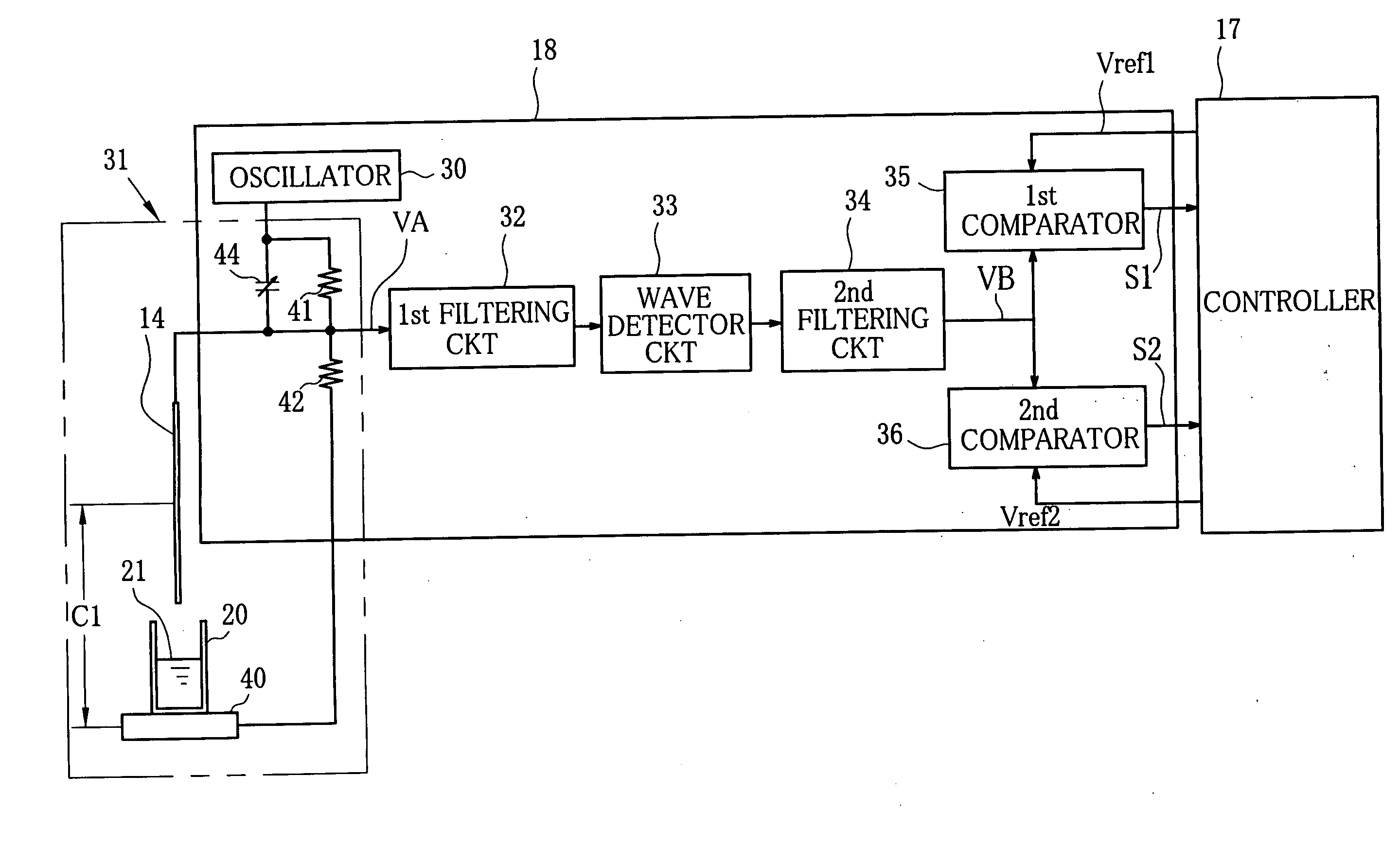
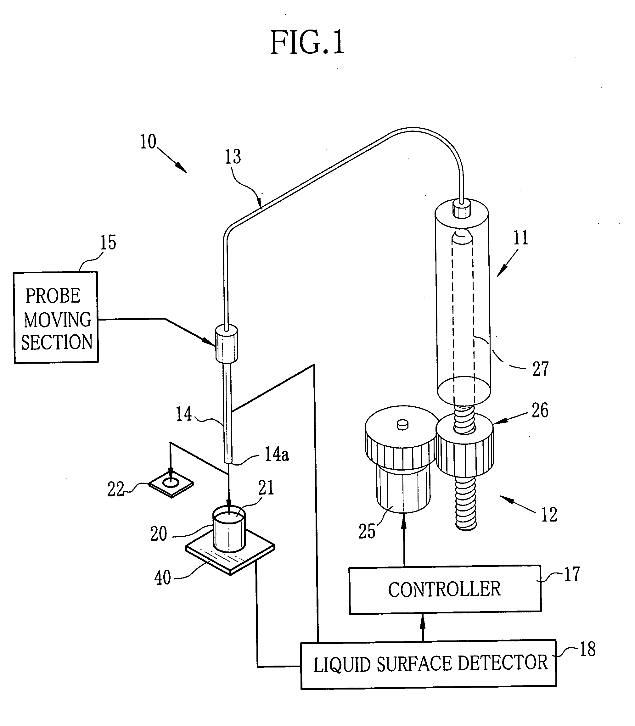
[0017] As shown in FIG. 1, a liquid supplier 10 is constituted of a syringe pump 11, a pump driver 12, an air tube 13, a suction probe 14, a probe moving section 15, a controller 17 and a liquid surface detector 18. The controller 17 controls the respective components based on a liquid surface detection signal from the liquid surface detector 18, to suck a liquid 21 from a sampling cup 20, which contains the liquid 21 as a specimen, into the suction probe 14, and then drop the sucked liquid 21 onto a test chip 22. A disposable tip member may be detachably attached to the suction probe 14, so as to change the tip member for one specimen from another.

[0018] The suction probe 14 is made of an electrically conductive material, and is set in the liquid supplier 10 with its tip 14a oriented downward and its upper end joined to one end of the air tube 13. Another end of the air tube 13 is connected to the syringe pump 11. The pump driver 12 drives the syringe pump 11. The pump driver 12 c...


PUM


Abstract

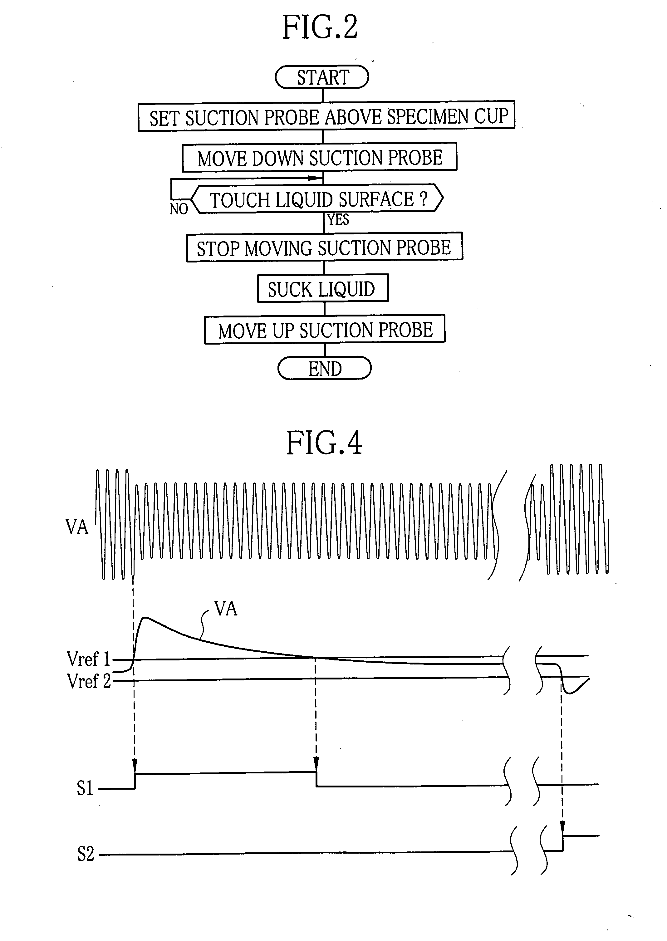
A liquid surface detector is constituted of an oscillator that outputs an alternating current signal at a frequency of 130 kHz, and a modulator circuit for modulating the alternating current signal with a capacitance index signal that indicates a change in capacitance. The capacitance changes with movement of a suction probe relative to a cup containing a liquid. An output signal of the modulator is filtered and amplified by a first filtering circuit that passes a frequency component of 130 kHz through it. Through a wave detector circuit and a second filtering circuit that passes a frequency component of 2 kHz, a signal corresponding to the capacitance index signal is detected from an output of the first filtering circuit, and is compared with a reference signal, to detect that the probe gets into contact with the liquid surface.

Description

FIELD OF THE INVENTION [0001] The present invention relates to a liquid surface detection device, which measures capacitance in order to judge whether a tip of a suction probe of an automatic analyzer or the like touches a surface of a liquid to suck, or not. BACKGROUND OF THE INVENTION [0002] In a conventional automatic analyzer, a suction probe is used to suck a small amount of liquid, such as reagent, specimen and diluent, from a cup, and inject it into another cup. If the tip of the suction probe is put deeply into the liquid to suck, the amount of the liquid adhering to the periphery of the probe becomes so much that it causes contamination, dropping or dispersing of the liquid from the probe in motion, or inexactness of the injection amount from the probe. In order to avoid such troubles, many conventional automatic analyzers are provided with a device for detecting accurately whether the tip of the suction probe comes into contact with the liquid surface, to stop excessive in...

Claims


Application Information

Patent Timeline
IPC IPC(8): G01F23/26G01B7/14G01N1/14G01N35/10
CPCG01F23/28G01N35/1011G01N2035/1025
Inventor KOBAYASHI, KAZUHISA
Owner FUJIFILM CORP
Learn More