
Solar battery system and thermoelectric hybrid solar battery system

a solar battery and hybrid technology, applied in the direction of hybrid energy generation, lighting and heating apparatus, and thermal radiation electric generators, etc., can solve the problems of 85% of solar energy not being used as usable energy in solar batteries, indirect adverse effects on the global environment, and high energy requirements, so as to improve the electric conversion efficiency, improve the efficiency of solar battery panel heating, and improve the effect of heat transferability

Inactive Publication Date: 2007-06-28
TAMA TLO LTD
View PDF6 Cites 57 Cited by
  • Summary
  • Abstract
  • Description
  • Claims
  • Application Information

AI Technical Summary

Benefits of technology

[0009] An object of the present invention is to provide a solar battery system capable of improving an efficiency of using solar energy comparing with that of conventional solar batteries by providing a cooling mechanism, and a thermoelectric hybrid solar battery system also capable of recovering heat energy from the cooling mechanism in addition to improving an efficiency of using as electric energy by the solar battery.
[0038] In the solar battery system of the present invention, a heat pipe having excellent heat transferability is arranged on a back surface of the solar battery panel and, by improving the electric conversion efficiency by lowering a temperature of the solar battery panel, the effect of utilizing solar energy is improved comparing with that in conventional solar batteries.
[0039] In the thermoelectric hybrid solar battery system of the present invention, a heat pipe having excellent heat transferability is arranged on a back surface of the solar battery panel and, in addition to improving the electric conversion efficiency by lowering the temperature of the solar battery panel, heat energy from the solar battery panel can be recovered, so that the effect of utilizing solar energy is improved comparing with that in conventional solar batteries.

Problems solved by technology

Supply sources of the electric energy are generated by thermal power and nuclear power, which directly and indirectly give considerable adverse effects on the global environment.
However, even though the solar energy is free and inexhaustible, much energy is necessary for producing solar batteries themselves.
Namely, 85% of solar energy cannot be used as usable energy in solar batteries.
In a current solar battery, wherein a temperature rise of the panel deteriorates the generating effect, the unused energy helps deterioration of the generating effect.

Method used


Image

  • Solar battery system and thermoelectric hybrid solar battery system
  • Solar battery system and thermoelectric hybrid solar battery system
  • Solar battery system and thermoelectric hybrid solar battery system

Examples


first embodiment

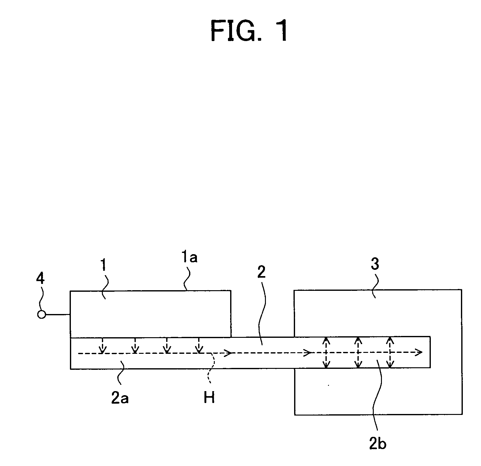
[0089]FIG. 1 is a schematic configuration view of a solar battery system according to the present embodiment.

[0090] The solar battery system of the present embodiment includes a solar battery panel 1, a heat pipe 2 and a heat release part 3.

[0091] The solar battery panel 1 receives sunlight on a light receiving surface la thereof and supplies power generated by photoelectric conversion to the outside from an external terminal 4, etc.

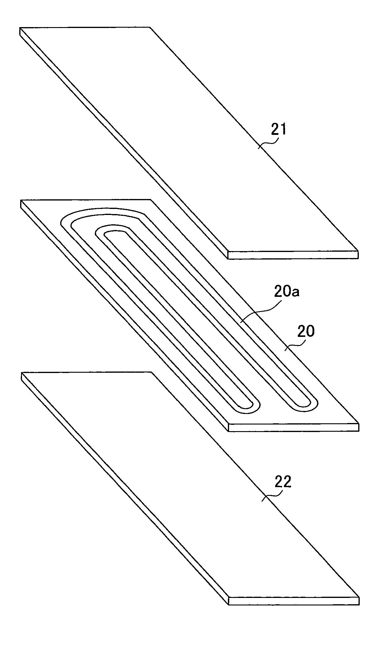
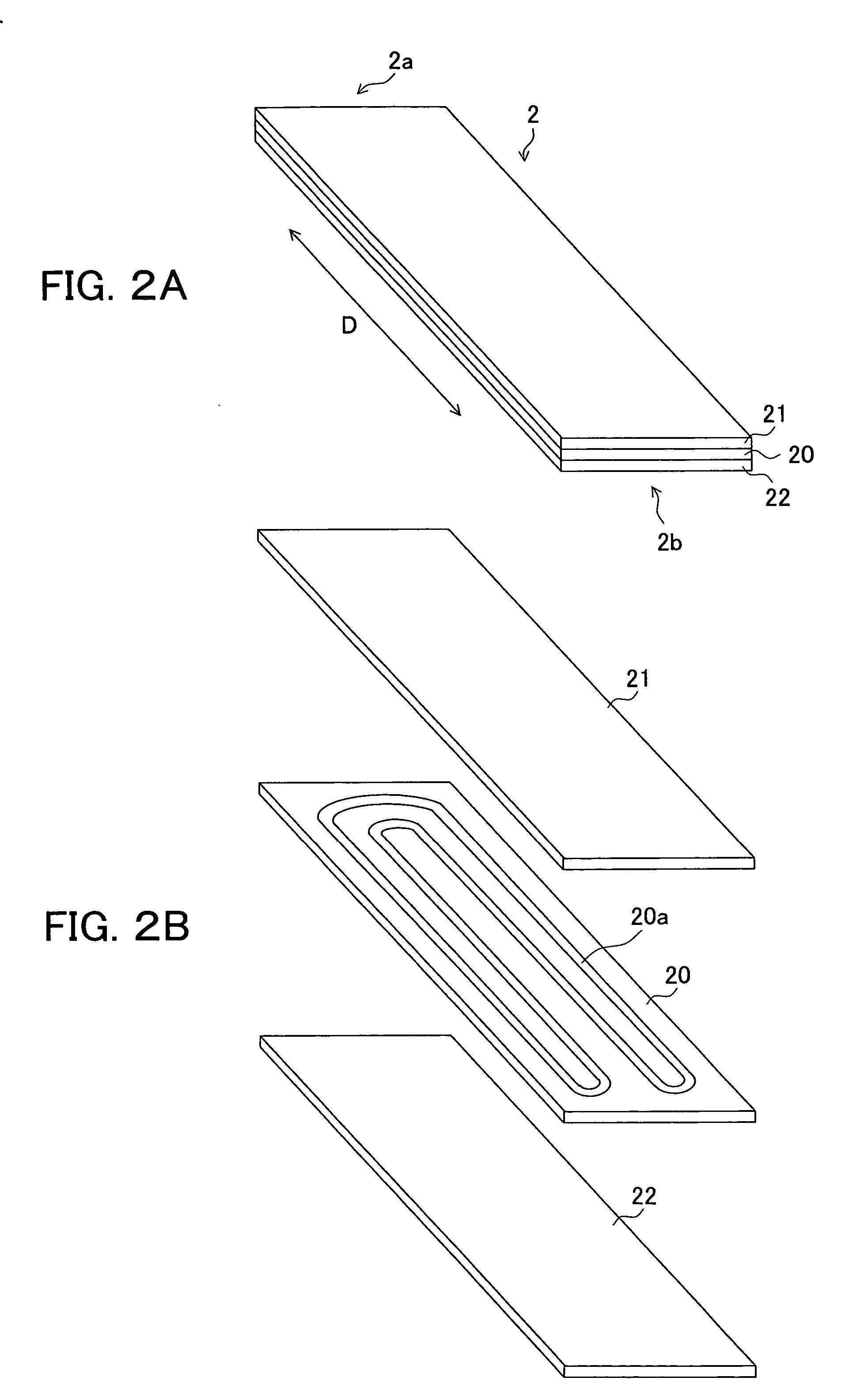
[0092] As shown in the schematic perspective view of FIG. 2A, the heat pipe 2 is configured to have a serpentine thin hole running some lengths between one end portion 2a and the other end portion 2b of a plate-shaped structure along the heat transfer direction D inside of the plate-shaped structure, and a refrigerant fluid is sealed in the serpentine thin hole. The serpentine thin hole is one loop-shaped thin hole arranged to be a serpentine shape.

[0093] For example, as shown in the schematic perspective view in FIG. 2A and the schematic view in FIG...

second embodiment

[0109]FIG. 5 is a schematic configuration view of a thermoelectric hybrid solar battery system according to the present embodiment.

[0110] The solar battery system of the present embodiment includes a solar battery panel 1, a heat pipe 2 and a tank-shaped hot water generation part 30 as a heat release part 3.

[0111] The solar battery panel 1 and the heat pipe 2 have the same configurations as those in the first embodiment.

[0112] The solar battery panel 1 receives sunlight on its light receiving surface 1a and supplies power generated by photoelectric conversion to the outside from the external terminal 4, etc.

[0113] The heat pipe 2 is configured to have a serpentine thin hole running some lengths between one end portion 2a and the other end portion 2b of a plate-shaped structure inside of the plate-shaped structure, and a refrigerant fluid is sealed in the serpentine thin hole. It is a so-called self-exciting mode oscillating-flow type heat pipe.

[0114] A surface of the plate-shap...

example 1

[0134] Based on the second embodiment explained as above, a thermoelectric hybrid solar battery system was produced.

[0135] Namely, to the back surface of the light receiving surface of a commercially available solar battery panel, one end portion of a Heatlane plate (made by TS Heatronics Co. Ltd.) was affixed as a plate-shaped self-exciting mode oscillating-flow type heat pipe via a copper plate having a thickness of 1.5 mm. At this time, the back surface of the solar battery panel was divided to fields, each having a width of two times a width of an area for affixing the solar battery panel to the heat pipe, that is, divided for every two times an area of the affixing surface, and the heat pipe was affixed to the center part of each field.

[0136] Also, at the other end portion of the heat pipe, a tank-shaped hot water generation part configured as shown in FIG. 5 was provided. A heat release fin was provided as a heat release accelerator on the surface of a part of the heat pipe ...


PUM


Abstract

A solar battery system with an improved effect of utilizing solar energy and a thermoelectric hybrid type solar battery system for furthermore recovering heat energy are provided. It is configured to include a solar battery panel 1 receiving sunlight at a light receiving surface 1a and supplying electricity generated by photoelectric conversion to the outside; a heat pipe 2 configured to have a serpentine thin hole provided therein with a sealed refrigerant fluid or configured to have a plate-shaped structure, for example, in a flat shape, a thin shape, furthermore, a thin film shape, wherein a surface of said plate-shaped structure on one end portion side is affixed to a back surface of said light receiving surface of said solar battery panel, and receiving heat H generated at said solar battery panel 1 from said one end portion 2a and conducting to the other end portion 2b; and a heat release part 3, such as a hot water generation part, receiving the heat from the other end portion 2b which is conducted in the heat pipe 2.

Description

TECHNICAL FIELD [0001] The present invention relates to a solar battery system and a thermoelectric solar battery system, and particularly relates to a solar battery system with improved electric conversion efficiency and a thermoelectric hybrid solar battery system for recovering heat energy in addition to electric energy. BACKGROUND ART [0002] Environmental destruction has been proceeding on a global basis and utilization of natural energy has become increasingly necessary for environmental conservation. Most of current consumer use energy is electricity. Supply sources of the electric energy are generated by thermal power and nuclear power, which directly and indirectly give considerable adverse effects on the global environment. [0003] Among a variety of power generation systems using natural energy, a solar battery is the most pervasive power generation system. [0004] As advantages of solar batteries, inexhaustible solar energy, excellent maintainability only requiring the init...

Claims


Application Information

Patent Timeline
Patent Type & Authority Applications(United States)
IPC IPC(8): H02N6/00F24S10/95F24S90/00
CPCF28D15/0233F28D15/0266H01L31/052H02S40/44Y02B10/20Y02E10/50Y02E10/60H01L35/30H01L31/0521H10N10/13
Inventor YADA, NAOYUKI
Owner TAMA TLO LTD
Learn More