Method and magnetic resonance system for adjustment of the field strength of RF pulses

a magnetic resonance system and field strength technology, applied in the field of methods for adjusting the field strength of radiofrequency pulses, can solve the problems of inability to assume, weak spatial dependency, and ambiguity in pulse calibration

Inactive Publication Date: 2007-06-28
SIEMENS HEATHCARE GMBH
View PDF4 Cites 24 Cited by
  • Summary
  • Abstract
  • Description
  • Claims
  • Application Information

AI Technical Summary

Benefits of technology

[0026] an amplitude determination unit that determines a pulse amplitude of the radio-frequency pulses, which pulse amplitude is adapted to the magnetic resonance measurement on the basis of the average value.
[0027] In principle any measurement values that represent the B1 field in the appertaining rod-shaped sub-volumes, i.e. at the appertaining location with regard to the extent direction, can be used as characteristic values. In a preferred exemplary embodiment a median flip angle in a strip of the test volume slice running perpendicularly to the spatial extent direction is determined as a characteristic value at a location along the extent direction, this median flip angle having been induced by the excitation in the appertaining volume strip. This means that here (as in the initial described method) the achieved flip angle is again averaged in a complex manner, such that regions overlap destructively due to phase variations. Since only one strip of the test volume slice is acquired (which is different than in the case described above), however, fewer phase variations occur than when such a complex averaging ensues over the entire two-dimensional volume of the test volume slice.
[0028] The averaging over the individual characteristic values within the considered segment can in principle ensue in a very simple manner. This means that, for example, all characteristic values are weighted equally. Alternatively, in the aver

Problems solved by technology

It cannot be assumed, however, that the RF field within the examination subject is homogenous due to the following influencing factors: Due to the interaction of the RF field with the human body, a homogeneous B1 distribution cannot be assumed, because of the differing dielectric and electrical properties of the various tissue types.
This spatial dependency is, however, only weakly developed in comparison to the aforementioned body inhomogeneity and is for the most part monotonous in its radial dependency.
In practice, it therefore represents only a subordinate problem for the pulse calibration, in particular at high field strengths.
This flip angle variation over the considered volume inevitably leads to an ambiguity in the pulse calibration.
If the flip angle required by a measurement sequence is regionally not achieved or is exceeded, this leads to a limited image quality in these regions, for examp

Method used


Image

  • Method and magnetic resonance system for adjustment of the field strength of RF pulses
  • Method and magnetic resonance system for adjustment of the field strength of RF pulses
  • Method and magnetic resonance system for adjustment of the field strength of RF pulses

Examples


Embodiment Construction

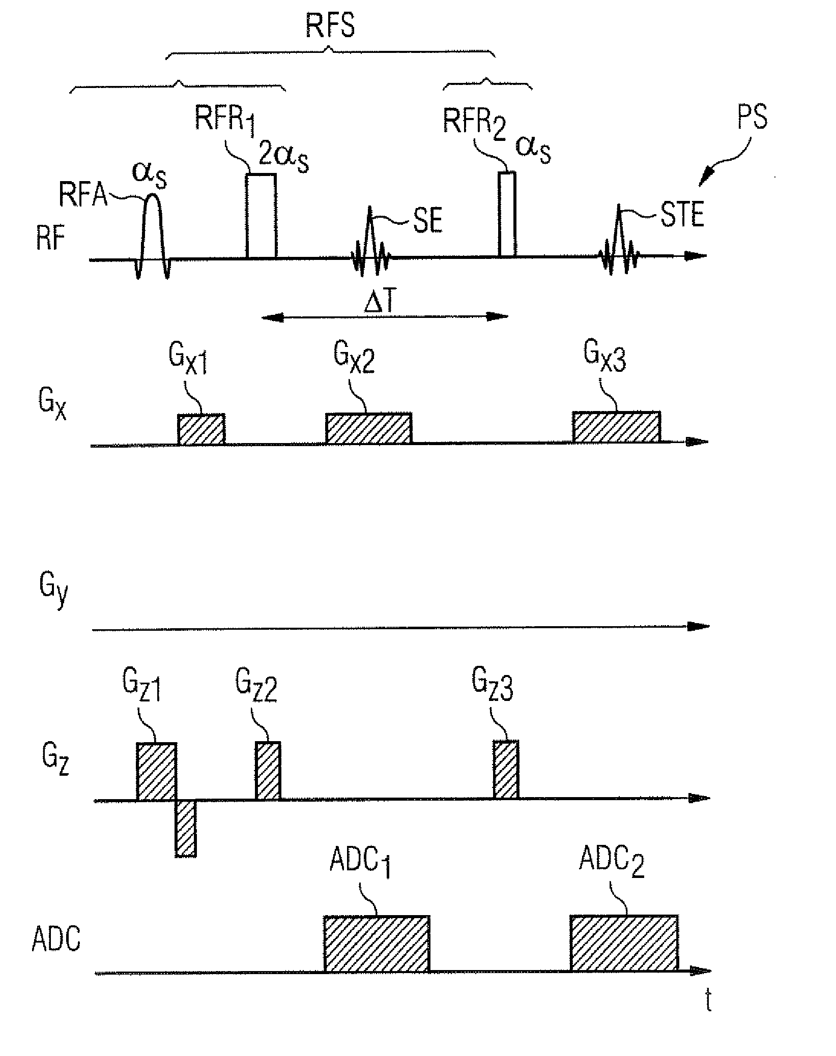
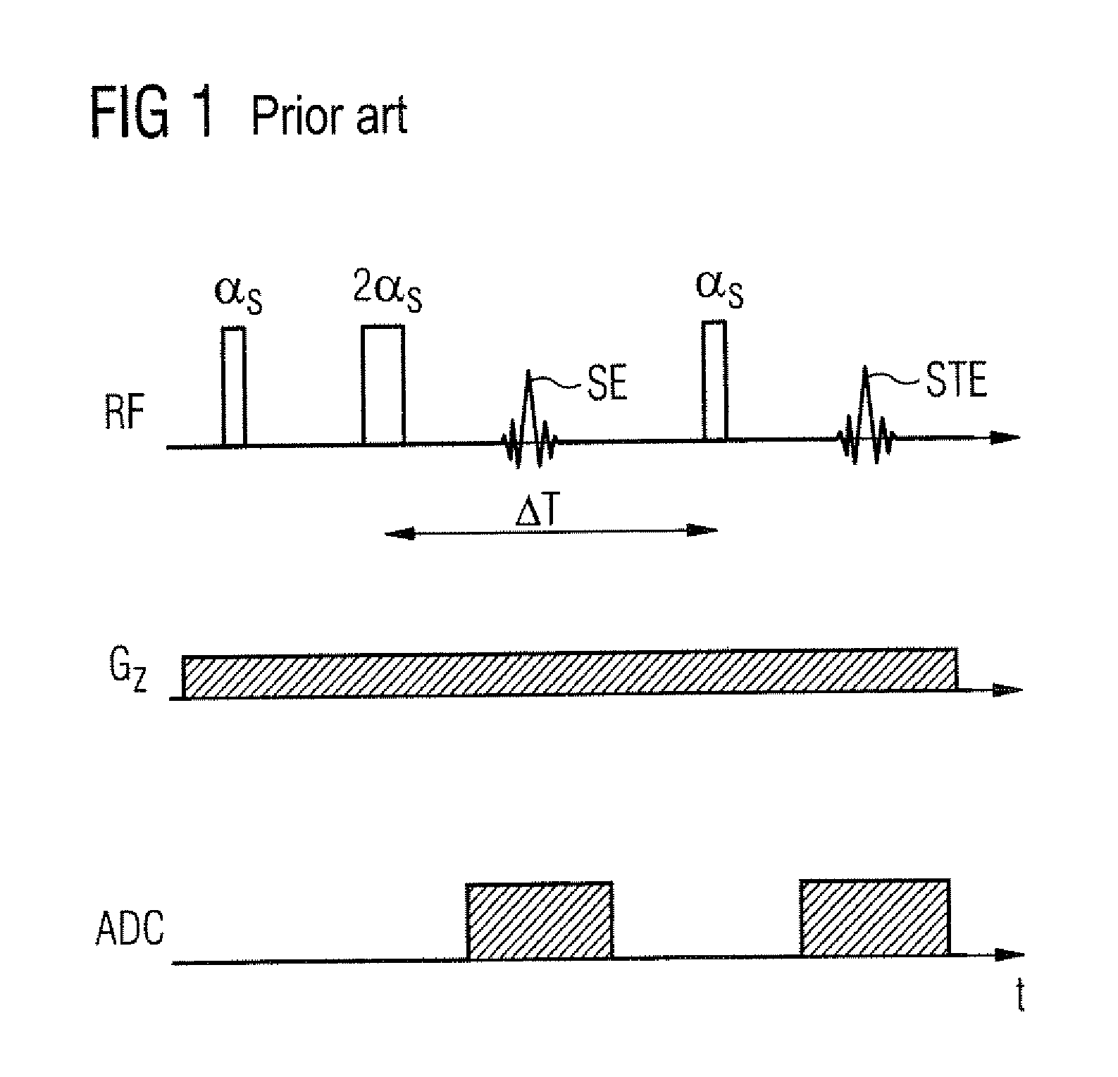
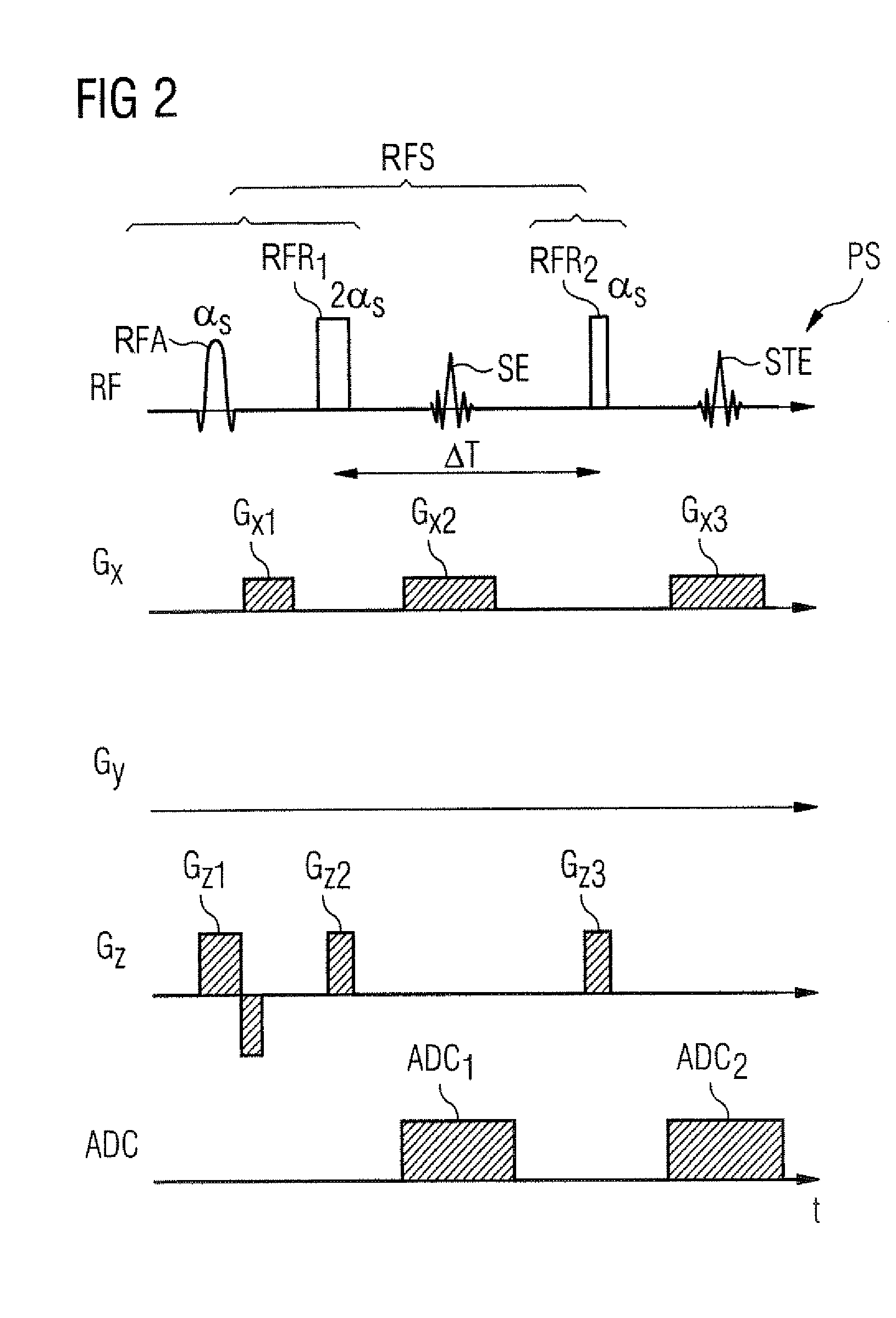
[0051] In the pulse sequence scheme shown in FIG. 1, the pulses emitted by the radio-frequency transmission antenna and the gradients appropriately switched in temporal dependence on the radio-frequency pulses are shown in a typical manner on parallel time axes (i.e. over time t).

[0052] The scheme shown in FIG. 1 is a typical scheme already explained above in order to determine an average flip angle within a slice volume according to the conventional manner. The radio-frequency pulses emitted by the radio-frequency transmission antenna are plotted on the uppermost axis designated with RF (radio-frequency). The gradient Gz shown under this is known as the slice-selection gradient, which is typically applied in the z-direction (i.e. in the direction of the basic magnetic field) and allows a selection of a specific slice or of a determined sub-volume upon excitation. The time windows in which a signal is measured with an ADC (analog-digital converter) are shown on the lowermost axis i...


PUM


Abstract

In a method for adjustment of the field strength of radio-frequency pulses as well as a magnetic resonance measurement system, radio-frequency pulses are emitted by a radio-frequency antenna of a magnetic resonance measurement system in a magnetic resonance measurement A test volume slice is initially excited by emission of radio-frequency pulses with a defined pulse amplitude by the appertaining radio-frequency antenna and one-dimensional, spatially-resolved characteristic values are determined along an extent direction of the test volume slice. The one-dimensional, spatially-resolved characteristic values respectively represent a local field strength of the B1 field in strips of the test volume slice running perpendicular to the extent direction. An average value of the determined characteristic values is then formed over at least over one determined segment along the extent direction of the test volume slice. A pulse amplitude of the radio-frequency pulses that is to be set for the magnetic resonance measurement to be implemented is determined on the basis of the average value.

Description

BACKGROUND OF THE INVENTION [0001] 1. Field of the Invention [0002] The invention concerns a method for adjustment of radio-frequency pulses which are emitted by a radio-frequency antenna of a magnetic resonance measurement system in a magnetic resonance measurement. Moreover, the invention concerns a magnetic resonance measurement system with a radio-frequency antenna and with a corresponding adjustment device for adjustment of the field strength of radio-frequency pulses that are emitted by the radio-frequency antenna in a magnetic resonance measurement. [0003] 2. Description of the Prior Art [0004] Magnetic resonance tomography has become a widespread technique for acquisition of images of the inside of the body of a living examination subject. In order to acquire an image with this method, i.e. to generate a magnetic resonance exposure of an examination subject, the body or the body part of the patient to be examined must initially be exposed to an optimally homogenous static ba...

Claims


Application Information

Patent Timeline
IPC IPC(8): G01V3/00
CPCG01R33/583G01R33/586
Inventor FEIWEIER, THORSTENHEUBES, PETERSPECKNER, THORSTEN
Owner SIEMENS HEATHCARE GMBH
Why Eureka
Try Eureka