Folded array CT baggage scanner

a baggage scanner and array technology, applied in the field of computed tomography (ct) scanner design, can solve the problems of cumbersome and expensive implementation of security measures using existing technology, increased labor intensity, and increased cost, and achieve the effect of reducing size, reducing labor intensity, and reducing cos

Inactive Publication Date: 2007-06-28
REVEAL IMAGING TECH
View PDF40 Cites 7 Cited by
  • Summary
  • Abstract
  • Description
  • Claims
  • Application Information

AI Technical Summary

Benefits of technology

[0011] The deficiencies of the prior art are substantially overcome by the CT scanner of the present invention which includes a wide angle x-ray tube and multiple sets of detectors. One set of detectors is centered on the x-ray source with one or more additional sets covering outer edges of the wide angle x-ray beam. The CT scanner of the present invention has a reduced size while maintaining the same tunnel size as conventional scanners. According to another aspect of the invention, the sets of detectors have different pitches in order to maintain a constant inter-detector angle. Thus, reconstruction algorithms can be simplified. According to another aspect of the invention, detectors are positioned on only half of the detector ring. According to another aspect of the invention, a second set of detectors sensitive to a different energy spectrum are positioned on the other half of the detector ring. The CT scanner of the present invention can provide dual energy analysis from a single scan of a bag, using the multiple sets of detectors.
[0012] According to another aspect of the invention, the x-ray source operates at a reduced flux level from conventional systems. Due to the compact size of the CT scanner of the invention, the shorter distances from the source to the detector allows for a less powerful x-ray. According to another aspect of the invention, a portion of a bag can be scanned multiple times with the results being averaged. The data from the multiple scans is averaged to remove noise. The resulting reduction in noise allows a reconstruction of heavy bags with a reduced flux x-ray source.

Problems solved by technology

EDS is faster, but more expensive and more prone to false alarms.
ETD is much slower, more invasive and requires more manual input.
Implementation of this security measure using existing technology has been and will continue to be cumbersome and expensive.
Even by the end of 2003, the implemented solutions are unlikely to be permanent solutions.
However, existing EDS machines are not easily deployed or integrated into existing baggage handling systems.
However, such systems require operator review of all images and provide slow throughput.
Furthermore, these systems also cannot provide thickness or density information for objects in order to provide explosive detection.
While CT technology is effective for explosive detection, use of existing CT technology in checked baggage inspection has many drawbacks.
They are large, heavy and require substantial space.
Furthermore, the system requires significant shielding, generally lead, to protect the operators and passengers from exposure to the powerful x-rays.
Implementation of known EDS systems for review of all baggage has proven to be difficult.
In many cases, the EDS system is installed in the lobby of the airport, where it occupies a great deal of space otherwise available to passengers, retails stores, and other security processes.
The large weight of the system often requires strengthened lobby floors.
However, such systems cost millions of dollars in infrastructure modifications and disruption of airport operations to install.
With multiple scanners, coordination of operation issues arise.

Method used


Image

  • Folded array CT baggage scanner
  • Folded array CT baggage scanner
  • Folded array CT baggage scanner

Examples


Embodiment Construction

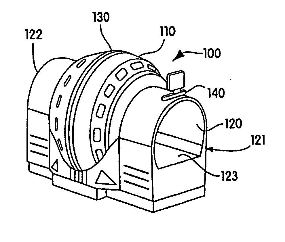
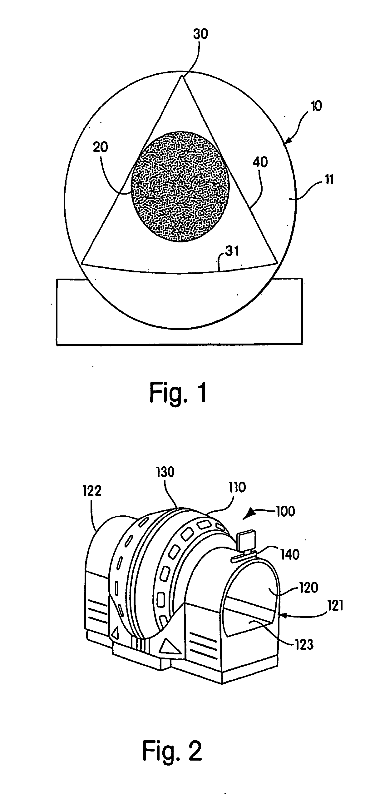
[0029] A CT scanner of the present invention has a more compact size than conventional scanners through the use of a wide angle x-ray source and a folded detector array, including sets of detector arrays at different distances from the x-ray source. FIG. 2 illustrates an embodiment of a CT scanner 100 according to an embodiment of the present invention. The CT scanner 100 includes a housing 110 with a substantially circular tunnel 120, there through. The tunnel 120 has an input end 121 and an output end 122. A conveyor 123 extends from the input end 121 to the output end 122 of the tunnel 120. For ease loading baggage, the conveyor may extend beyond the ends of the tunnel 120. Additionally, other conveyors may be positioned and used to transfer baggage to or from the conveyor 123 in the CT scanner 100. Coverings (not shown), such as lead lined rubber or fabric, may be placed within the tunnel 120 or at the input end 121 and output end 122, to provide x-ray shielding. The CT scanner ...


PUM

PropertyMeasurementUnit
diameteraaaaaaaaaa
diameteraaaaaaaaaa
diameteraaaaaaaaaa

Abstract

A reduced size CT scanner for baggage inspection has a wide angle x-ray source and multiple sets of detectors at different distances from the x-ray source. The detectors in each set are sized and positioned to maintain consistent pitch and flux levels among all detectors. Conventional reconstruction processes can be used to process the data from the CT scanner. The scanner may also be incorporated into a check-in desk in a network of scanners.

Description

RELATED APPLICATIONS [0001] This continuation application claims priority to U.S. application Ser. No. 10 / 677,976, filed Oct. 2, 2003, which is incorporated by reference in its entirety.BACKGROUND OF THE INVENTION [0002] 1. Field of the Invention [0003] The present invention relates to a Computed Tomography (CT) system for inspecting baggage for explosives or other contraband. More particularly, it relates to a novel Computed Tomography (CT) scanner design having a reduced size. [0004] 2. Discussion of Related Art [0005] Following the terrorist attacks on Sep. 11, 2001, the United States government decided to implement additional airport security. One of the security measures which were to be implemented was inspection of all checked baggage for explosives. In November 2001, Congress passed the Aviation and Transportation Security Act, which mandated 100% explosive detection screening of checked baggage by Dec. 31, 2002. It was expected that the screening requirements would be met t...

Claims


Application Information

Patent Timeline
Patent Type & Authority Applications(United States)
IPC IPC(8): H05G1/60A61B6/00G01N23/00G21K1/12
CPCA61B6/4266A61B6/482G01V5/0041G01V5/005
Inventor ELLENBOGEN, MICHAELBIIJANI, RICHARD ROBEHR
Owner REVEAL IMAGING TECH
Why Eureka
Try Eureka