

Semiconductor device, display device, and electronic device
- Summary
- Abstract
- Description
- Claims
- Application Information
AI Technical Summary
Benefits of technology
Problems solved by technology
Method used
Image

Examples
embodiment modes
[0086] Embodiment Modes of the present invention will be described with reference to the drawings. Note that the present invention can be embodied with many different modes, and it is easily understood by those skilled in the art that the modes and details can be variously modified without departing from the spirit and scope of the present invention. Therefore, the present invention should not be construed as being limited to the description of the Embodiment Modes. In the structures of the invention described hereinafter, the same reference numerals are given to the same parts or parts having similar functions in different drawings, and the description of such parts will not be repeated.
embodiment mode 1
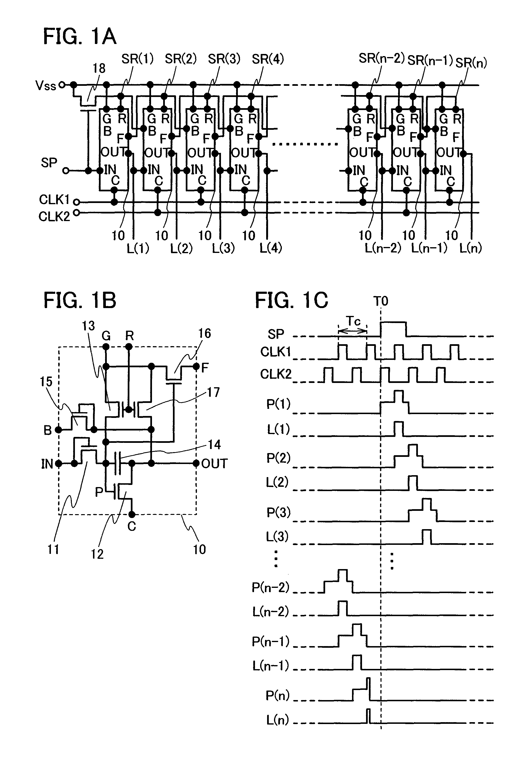
[0087] In this embodiment mode, a circuit configuration of a shift register where the electric potential of an output terminal is fixed to a non-selection period, thereby reducing the occurrence of malfunctions due to clock signals or noise, will be described. Circuit configuration examples of a shift register of the present invention are shown in FIGS. 1A to 1C. FIG. 1A shows the entire circuit configuration of a shift register circuit of the present invention. FIG. 1B shows a configuration example of a circuit 10 which shows a single stage circuit of a shift register of the present invention. Note that in this specification, a single stage circuit refers to a minimum unit for forming a circuit, which corresponds to an output terminal (L(1) to L(n)) of the circuit, as does FIG. 1B with respect to FIG. 1A. FIG. 1C shows waveforms of an input signal, an internal electrode, and an output signal in the circuit shown in FIGS. 1A and 1B.
[0088] The circuit shown in FIG. 1A is provided wi...
embodiment mode 2
[0152] In this embodiment mode, reset operation of the last stage and the reset operation of all the stages of the shift register circuit of the present invention will be described.
[0153] In the circuit configuration described in Embodiment Mode 1, the reset operation of the current stage is conducted at the timing of the operation of the next stage. Here, since there is no stage after the shift register circuit at the last stage, no pulse defining the timing of the reset operation is inputted to the last stage. Therefore, the electric potential of the electrode SR(n) will not be at H level by reset operation. Accordingly, clock signals are constantly outputted to the terminal OUT of the last stage.
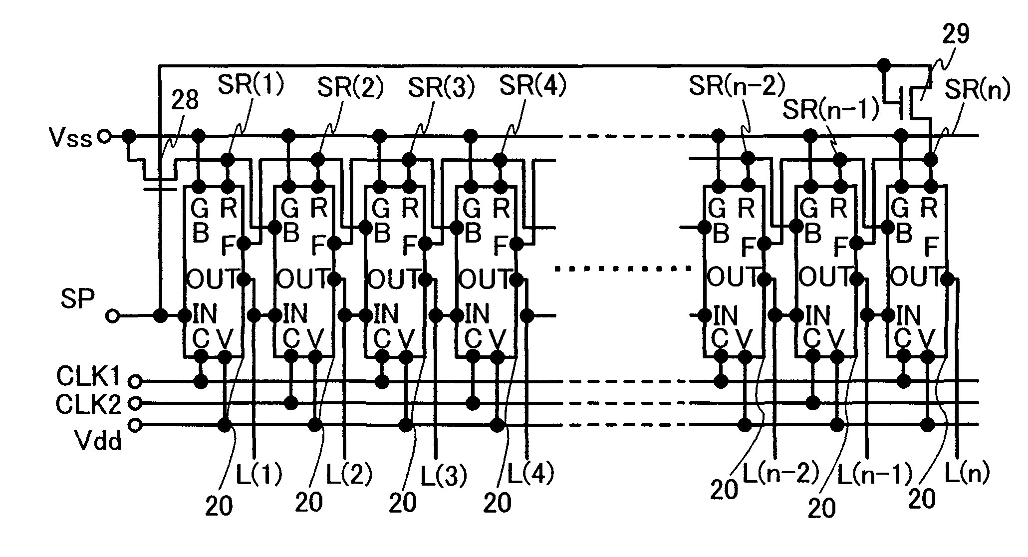
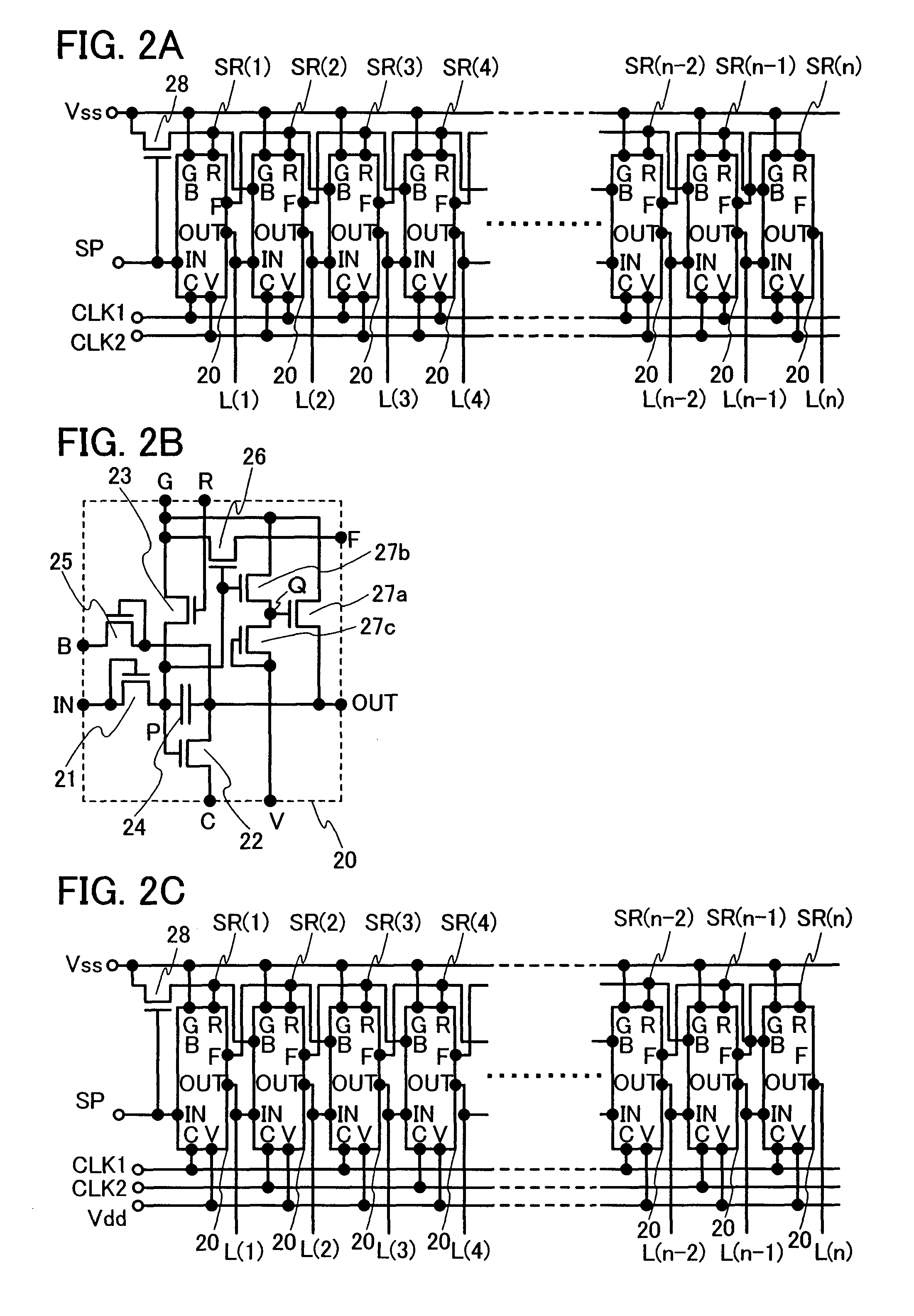
[0154] Considering the points, in Embodiment Mode 1, the electrode SR(n) is connected to the electrode SR(n−1) as shown in FIG. 1A, FIG. 2A, and FIG. 2C. Thus, reset operation can be performed by making the electrode SR(n) at H level with the output of the terminal OUT at the last stage...
PUM
 Abstract
Description
Claims
Application Information