Support separators for high performance communications cable with optional hollow tubes for; blown optical fiber, coaxial, and/or twisted pair conductors

a technology of support separators and high-performance communications cables, which is applied in the direction of insulated conductors, cables, instruments, etc., can solve the problems of increased cross-talk, unsatisfactory energy transfer between conductor pairs, and shielded cables, etc., and achieves the effect of sufficient strength

Inactive Publication Date: 2007-07-05
CABLE COMPONENTS GROUP
View PDF22 Cites 11 Cited by
  • Summary
  • Abstract
  • Description
  • Claims
  • Application Information

AI Technical Summary

Benefits of technology

[0068] This invention provides a lower cost communications cable and / or a support separator for the communications cable exhibiting improved electrical, flammability, and optionally, optical properties. The cable or separator or cable with one or more separators have interior support(s) extending along the longitudinal length of the communications cable. The interior support has a central region extending along the longitudinal length of the interior support. In a preferred configuration, the cable includes a geometrically symmetrical core with a central circular ring region with various extending protrusions for pair separation and derivatives thereof. The central ring portion can optionally include a hollow region to act as an air blown fiber (ABF) duct which is available for filling with optical fiber.

Problems solved by technology

Energy transferred between conductor pairs is undesirable and referred to as crosstalk.
Such close spacing increases the amount of undesirable cross-talk that occurs.
Shielded cable, although exhibiting better cross-talk isolation, is more difficult, time consuming and costly to manufacture, install, and terminate.
Individually shielded pairs must generally be terminated using special tools, devices and techniques adapted for the job, also increasing cost and difficulty.
However, UTP fails to achieve superior cross-talk isolation such as required by the evolving higher frequency standards for data and other state of the art transmission cable systems, even when varying pair lays are used.
The various pairs of the cable are therefore separated from each other, but each is only partially shielded, which is not so effective as shielding around each pair and is not always satisfactory.
However, these core types can add substantial cost to the cable, as well as excess material mass which forms a potential fire hazard, as explained below, while achieving a crosstalk reduction of typically 3 dB or more.
The movement occurs when the cable is put on new reels or on a reelex box during installation and stress on the conductor may cause electrical degradation.
This undesirable separation contributes to increased structural return loss (SRL) and more variation in impedance.
This method has been proven impractical because such tight lays are expensive and greatly limit the cable manufacturer's throughput and overall production yield.
Secondly, using the fluid drag of a gaseous medium produces a distributed pulling force on the fiber (wire) member.
With respect to ABF installation, such projections have been observed to reduce surface area contact between the cable and tubing sidewall, which results in corresponding decreased friction as the cable is blown through the tubing.
While the above described conventional cable, including the Belden 1711A cable design, due in part to their use of fluorinated polymers, meets all of the above design criteria, the use of fluorinated polymers is extremely expensive and may account for up to 60% of the cost of a cable designed for plenum usage.
A solid core of these communications cables contributes a large volume of fuel to a potential cable fire.
Forming the core of a fire resistant material, such as with FEP (fluorinated ethylene-propylene), is very costly due to the volume of material used in the core, but it should help reduce flame spread over the 20 minute test period.
In addition, they also exhibit inferior resistance to burning and generally produce more smoke than FEP under burning conditions.
Data cables have also used very complex lay techniques to cancel E and B (electric and magnetic fields) to control NEXT.
Use of the above techniques to control electrical characteristics have inherent problems that have lead to various cable methods and designs to overcome these problems.
This is especially true since many conventional design concepts, fillers, and spacers may not provide sufficient cross-talk at the higher frequencies.
Individual shielding is costly and complex to process.
Individual shielding is highly susceptible to geometric instability during processing and use.
In addition, the ground plane of individual shields, 360° in ISTP's—individually shielded twisted pairs—is also an expensive process.
Lay techniques and the associated multi-shaped anvils of the present invention to achieve such lay geometries are also complex, costly and susceptible to instability during processing and use.
Another problem with many data cables is their susceptibility to deformation during manufacture and use.
Deformation of the cable geometry, such as the shield, also potentially severely reduces the electrical and optical consistency.
For multi-media cable, i.e. cable that contains both metal conductors and optical fibers, the set of criteria is often incompatible.
In addition, fragile optical fibers are susceptible to mechanical damage without crush resistant members (in addition to conventional jacketing).

Method used


Image

  • Support separators for high performance communications cable with optional hollow tubes for; blown optical fiber, coaxial, and/or twisted pair conductors
  • Support separators for high performance communications cable with optional hollow tubes for; blown optical fiber, coaxial, and/or twisted pair conductors
  • Support separators for high performance communications cable with optional hollow tubes for; blown optical fiber, coaxial, and/or twisted pair conductors

Examples


second embodiment

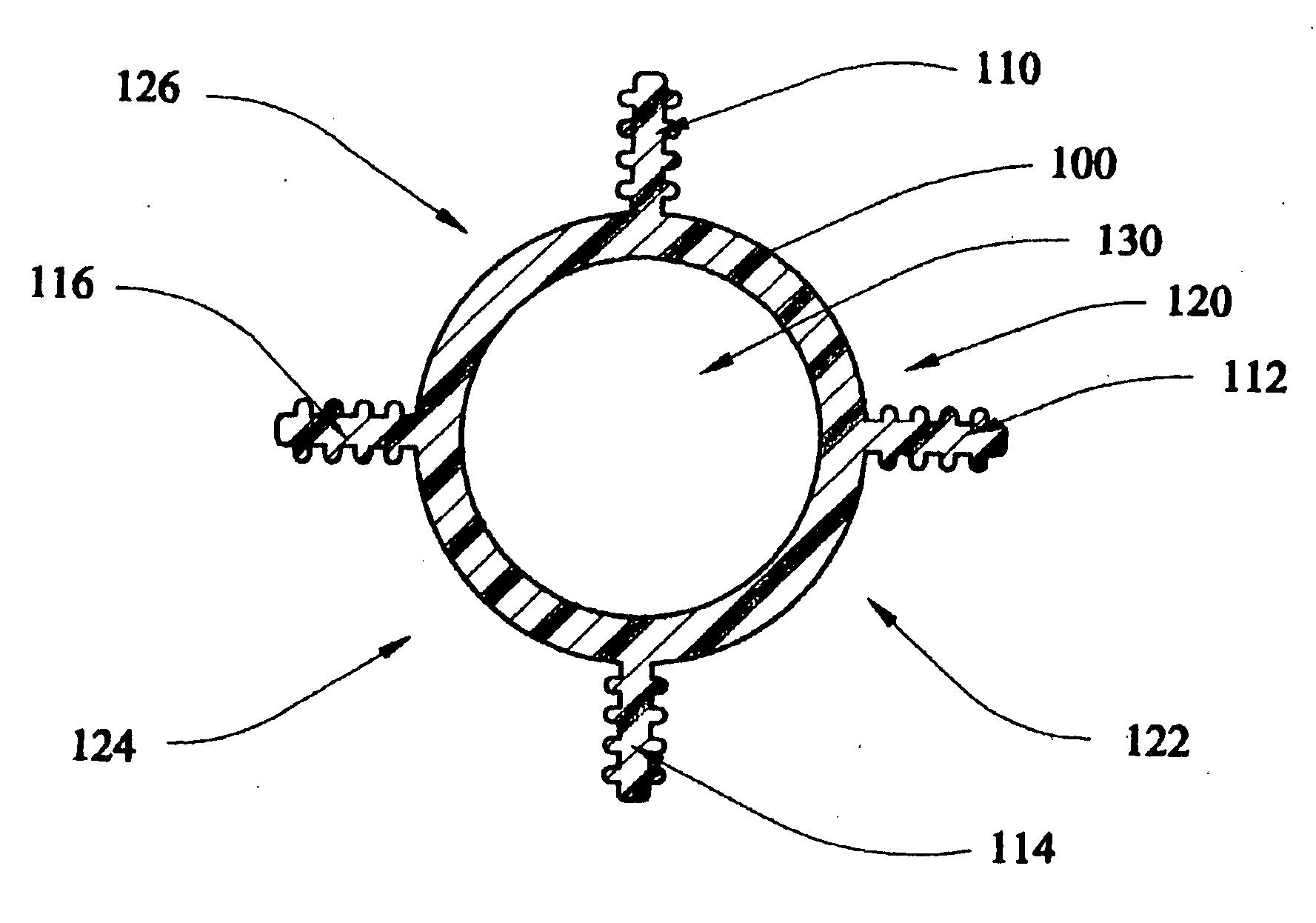
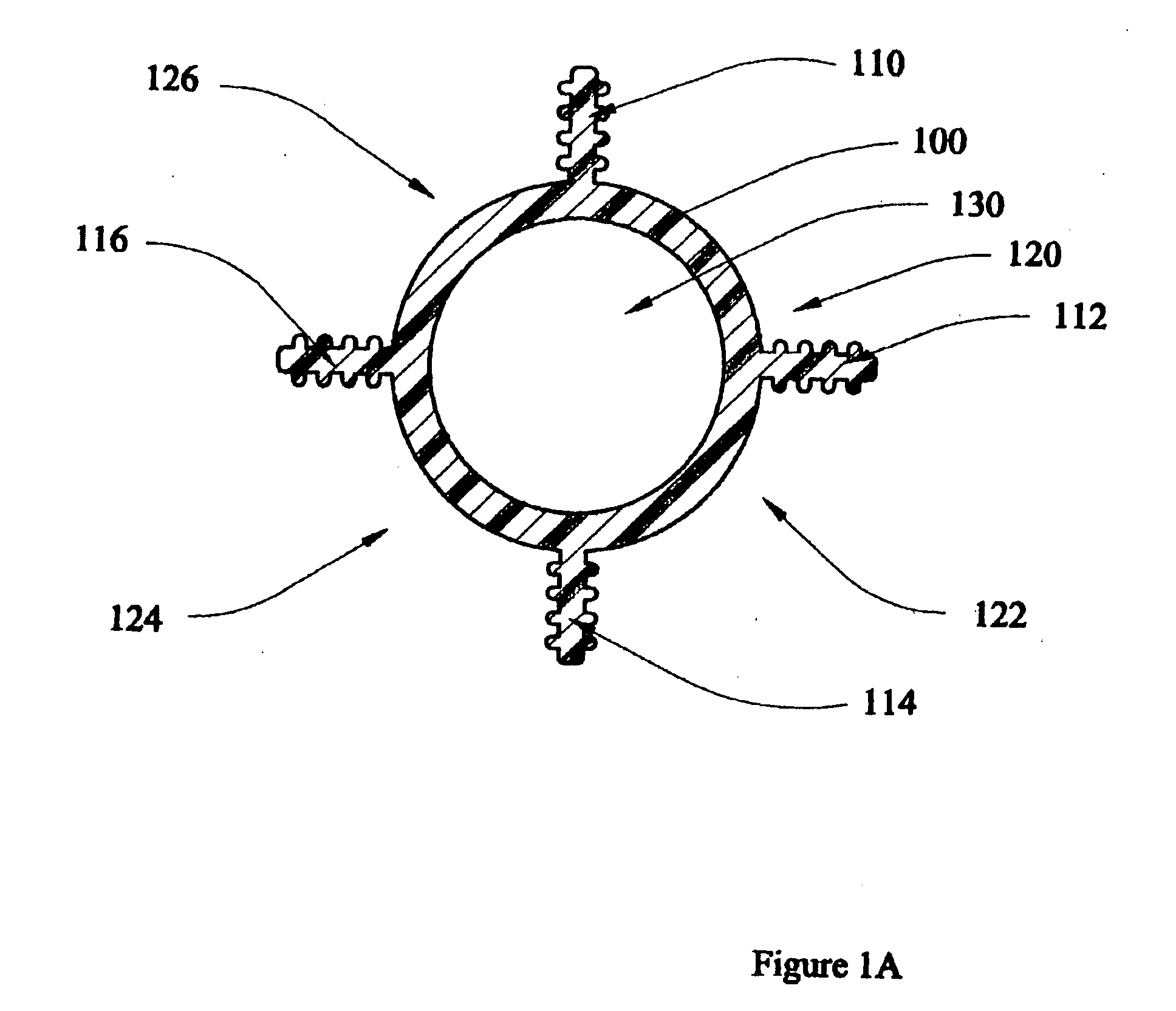
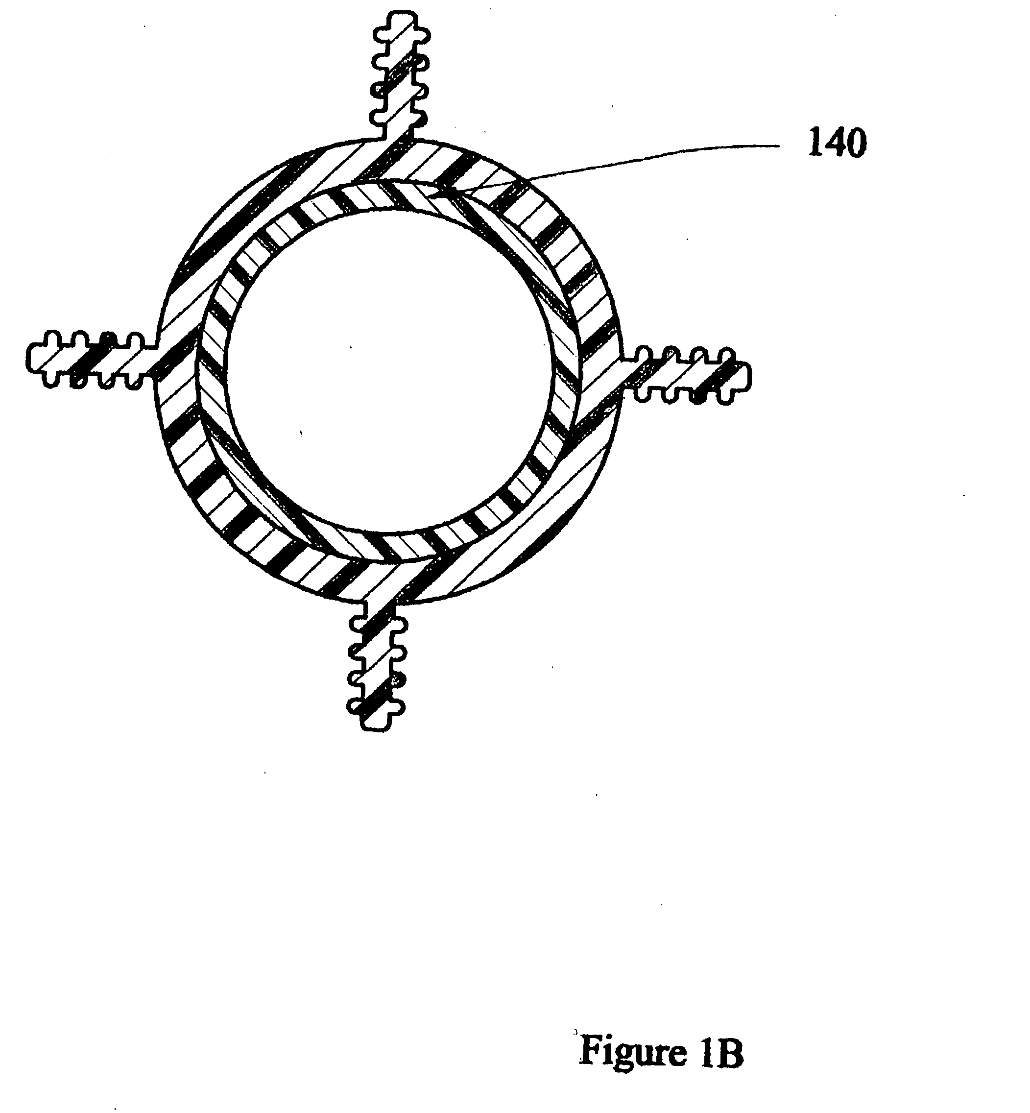
[0133]FIG. 1B is a cross-section view of the cable support-separator that includes the same symmetrical core with a central circular ring region as for FIG. 1A, but also includes a second inner ring (140) within the hollow region comprised of a different material than the outer ring for either increasing lubricity or friction with four extending rifled protrusions each extending in a preferred 90 degree separation from each other for optimum pair separation.

third embodiment

[0134]FIG. 1C is a cross-section view of the cable support-separator that includes the same symmetrical core with a central circular ring region as for FIG. 1A, but also includes a second inner ring within the hollow region comprised of a different material than the outer ring for increasing friction utilizing rifled inner spatially arranged sections (150) with four extending rifled protrusions each extending in a preferred 90 degree separation from each other for optimum pair separation.

fourth embodiment

[0135]FIG. 1D is a cross-section view of the cable support-separator that includes the same symmetrical core with a central circular ring region as for FIG. 1C, but also includes the optional use of a organic or inorganic fibers (160) including polyamide (for example Kevlar®) filling and an optional strength member within the second inner ring within the hollow region comprised of a different material than the outer ring as well as allowing for multiple separate multimode or single mode fiber optic units (162) also contained within the same hollow region with four extending rifled protrusions each extending in a preferred 90 degree separation from each other for optimum pair separation.


PUM

PropertyMeasurementUnit
frequenciesaaaaaaaaaa

Abstract

A high performance communications cable with core support-separators having various shaped profiles defining and maintaining a space between transmission multi-media or transmission multi-media pairs. The core may be of a conductive or insulative material. The central core region includes a hollow opening or duct for blown fiber (ABF). The core support-separator can be interior to the cable jacket or without the benefit of a jacket. A thin layer of material can act as a type of skin for future mechanical protection. The specially shaped core support-separator has a central region that is either solid, partially solid, foamed, with a solid skin over the foam or hollow itself. The cable may include a plurality of shaped sections that extend outward from the central region along the length of the central region. Each of the defined clearance channels allow for disposal therein of conductors and optical fibers.

Description

CLAIM TO PRIORITY [0001] Applicants hereby claim priority under all rights to which they are entitled under 35 U.S.C. Section 120 based upon the U.S. Provisional Application Ser. No. 60 / 462,983 for this patent application filed at the United States Patent and Trademark Office on Apr. 15, 2003.FIELD OF INVENTION [0002] This invention relates to high performance multi-media communications cables utilizing paired or unpaired electrical conductors with or without optical fibers, and / or coaxial conductors and / or twisted pair conductors. The metal conductors may be shielded or unshielded or a combination of both depending on the utility requirements. More particularly, it relates to support-separators or spacers for cables, which may perform as self-contained cables, having a central core defining singular or plural individual pair channels with allowance for hollow tubes that may initially be void of, or filled with one or more fiber optic, coaxial, or twisted pair conductors. The tubes ...

Claims


Application Information

Patent Timeline
Patent Type & Authority Applications(United States)
IPC IPC(8): H01B7/00G02B6/44H01B11/04H01B11/22
CPCG02B6/4459H01B11/22H01B11/04G02B6/4489
Inventor GLEW, CHARLES A.
Owner CABLE COMPONENTS GROUP
Why Eureka
Try Eureka