Radiation source

a radiation source and source technology, applied in the field of radiation sources, can solve the problems of difficult to maintain a low pressure in the vicinity of the discharge, ineffective pumping to reduce the pressure of the source environment, and typical gas buffer provided

Inactive Publication Date: 2007-07-05
ASML NETHERLANDS BV
View PDF6 Cites 24 Cited by
  • Summary
  • Abstract
  • Description
  • Claims
  • Application Information

AI Technical Summary

Benefits of technology

[0007] It is desirable to provide a radiation source th...

Problems solved by technology

A first problem is that a gas buffer is typically provided near the discharge area to stop debris from the discharge reaching other components.
The buffer gas flushed towards the discharge area makes it difficult to maintain a low pressure in the vicinity of the discharge.
Another problem is that the discharge area needs to be shielded from the environment and previously a metal plate surrounding the discharge area has been provided in ...

Method used


Image

  • Radiation source
  • Radiation source
  • Radiation source

Examples


Embodiment Construction

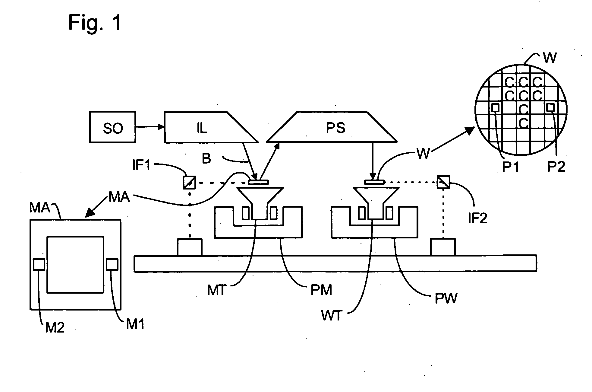
[0021]FIG. 1 schematically depicts a lithographic apparatus according to one embodiment of the invention. The apparatus includes a collector CO configured to collect radiation from a radiation source SO. An illumination system (illuminator) IL is configured to condition a radiation beam B (e.g. UV radiation or EUV radiation). A support (e.g. a mask table) MT is configured to support a patterning device (e.g. a mask) MA and is connected to a first positioner PM configured to accurately position the patterning device, in accordance with certain parameters. A substrate table (e.g. a wafer table) WT is configured to hold a substrate (e.g. a resist-coated wafer) W and is connected to a second positioner PW configured to accurately position the substrate in accordance with certain parameters. A projection system (e.g. a refractive projection lens system) PS is configured to project a pattern imparted to the radiation beam B by patterning device MA onto a target portion C (e.g. including o...


PUM


Abstract

A radiation source generates short-wavelength radiation, such as extreme ultraviolet radiation, for use in lithography. Rotating electrodes are provided which dip into respective baths of liquid metal, for example, tin. An electrical discharge is produced between the electrodes to generate the radiation. Holes are provided in the electrodes and/or in a metal shielding plate around the electrodes to enable better pumping down to low pressure in the vicinity of the discharge to improve the conversion efficiency of the source. The holes in the electrodes improve cooling of the electrodes by causing stirring of the liquid metal, and by improving the thermal and electrical contact between the electrodes and the liquid metal. Improved electrical contact also reduces the time-constant of the discharge circuit, thereby further improving the conversion efficiency of the source.

Description

BACKGROUND OF THE INVENTION [0001] 1. Field of the Invention [0002] The present invention relates to a radiation source, for example for producing extreme ultraviolet radiation (EUV) or soft X-ray radiation, which may be used in lithography. [0003] 2. Description of the Related Art [0004] A lithographic apparatus is a machine that applies a desired pattern onto a substrate, usually onto a target portion of the substrate. A lithographic apparatus can be used, for example, in the manufacture of integrated circuits (ICs). In that instance, a patterning device, which is alternatively referred to as a mask or a reticle, may be used to, generate a circuit pattern to be formed on an individual layer of the IC. This pattern can be transferred onto a target portion (e.g. including part of, one, or several dies) on a substrate (e.g. a silicon wafer). Transfer of the pattern is typically via imaging onto a layer of radiation-sensitive material (resist) provided on the substrate. In general, a ...

Claims


Application Information

Patent Timeline
IPC IPC(8): G21G4/00
CPCG03F7/70033H05G2/005H05G2/003
Inventor MOORS, JOHANNES HUBERTUS JOSEPHINABANINE, VADIM YEVGENYEVICHFRANKEN, JOHANNES CHRISTIAAN LEONARDUSIVANOV, VLADIMIR VITALEVITCHKOSHELEV, KONSTANTIN NIKOLAEVITCHSTRUYCKEN, ALEXANDER MATTHIJS
Owner ASML NETHERLANDS BV
Why Eureka
Try Eureka