Method of manufacturing continuous disk winding for high-voltage superconducting transformers

a superconducting transformer and continuous disk technology, applied in the direction of superconducting magnets/coils, superconductor devices, magnetic bodies, etc., can solve the problems of reducing the efficiency of the wire and reducing the loss of the wire, and achieve the effect of no joint and low loss

Active Publication Date: 2007-07-05
SUNAM
View PDF3 Cites 9 Cited by
  • Summary
  • Abstract
  • Description
  • Claims
  • Application Information

AI Technical Summary

Benefits of technology

[0009] Therefore, the present invention has been made in view of the above problems, and it is an object of the present invention to provide a method of manufacturing a continuous disk winding for high-voltage superconducting transformers that has special features of no joint and low loss, which are advantages of a layer winding, while being formed in the shape of a disk winding, which is advantageous in voltage distribution and insulation.

Problems solved by technology

The continuous disk winding is manufactured by winding a high-temperature superconducting wire in the shape of a disk such that the winding is continuously carried out without joining, thereby reducing the reduction in efficiency of the wire due to the joining and reducing loss of the wire.

Method used


Image

  • Method of manufacturing continuous disk winding for high-voltage superconducting transformers
  • Method of manufacturing continuous disk winding for high-voltage superconducting transformers
  • Method of manufacturing continuous disk winding for high-voltage superconducting transformers

Examples


Embodiment Construction

[0027] Now, preferred embodiments of the present invention will be described in detail with reference to the accompanying drawings.

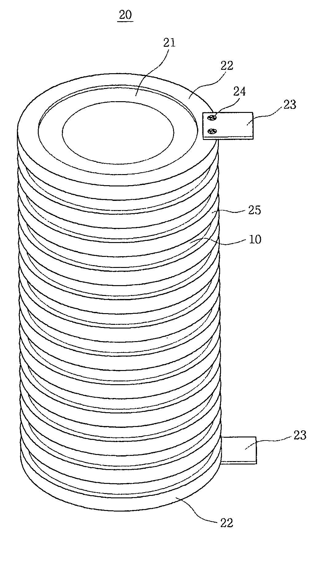
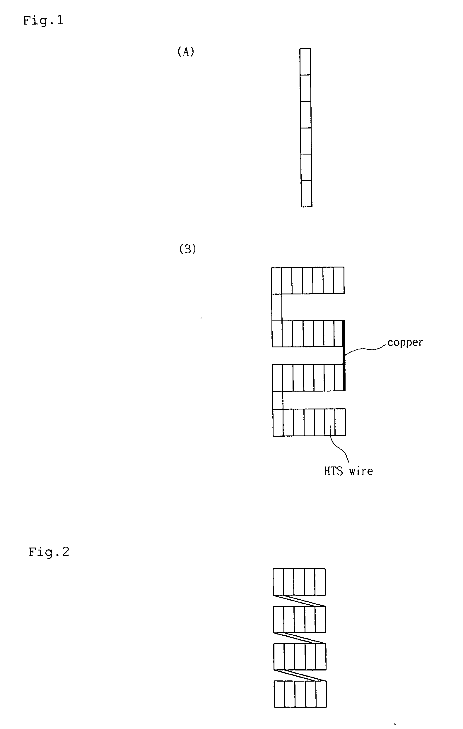
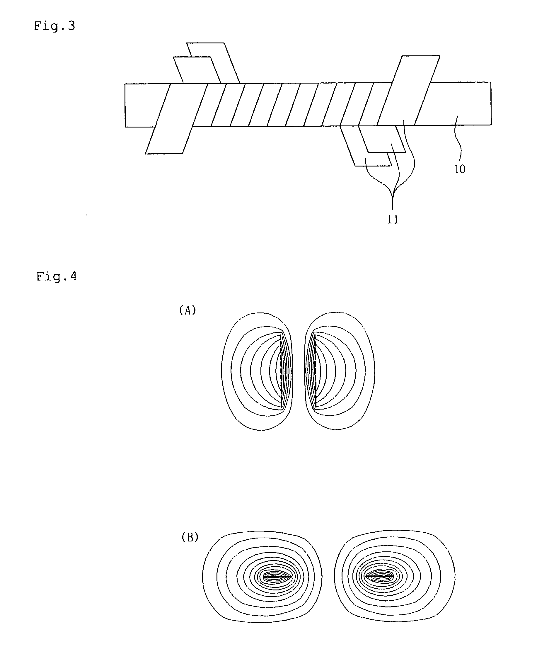
[0028]FIG. 2 is a view illustrating a continuous disk winding for high-voltage superconducting transformers according to the present invention, FIG. 3 is a view illustrating a method of insulating a high-temperature superconducting wire according to the present invention, FIG. 4A is a view illustrating the distribution of a magnetic field in a continuous disk winding according to the present invention, FIG. 4B is a view illustrating the distribution of a magnetic field in a conventional disk winding, FIG. 5 is a graph illustrating the relationship between current and a magnetic field for estimating critical current according to the present invention, FIG. 6 is a graph illustrating the comparison between alternating current loss of a continuous disk winding according to the present invention and alternating current loss of a conventional disk winding, FI...


PUM

PropertyMeasurementUnit
heightaaaaaaaaaa
heightaaaaaaaaaa
outer diameteraaaaaaaaaa

Abstract

Disclosed herein is a method of manufacturing a continuous disk winding for high-voltage superconducting transformers that has special features of no joint and low loss, which are advantages of a layer winding, while being formed in the shape of a disk winding, which is advantageous in voltage distribution and insulation. The method includes lapping a high-temperature superconducting wire using Kapton films to apply multiple layers of insulation around the high-temperature superconducting wire, fixing one end of the high-temperature superconducting wire to a current inlet terminal of a bobbin, to the lower end of which is attached a fixing plate, which has the current inlet terminal, and winding the high-temperature superconducting wire on the bobbin by the predetermined number of turns, fitting a disk having a slit formed therein onto the bobbin to form high-temperature superconducting wire layers, inserting the high-temperature superconducting wire into a front end of the slit of the fitted disk and moving high-temperature superconducting wire to a rear end of the slit such that the high-temperature superconducting wire can be wound on the next layer by the predetermined number of turns, fitting a plurality of disks, each of which has a slit formed therein, onto the bobbin at predetermined intervals to form a plurality of high-temperature superconducting wire layers, and repeatedly winding the high-temperature superconducting wire for each disk such that the high-temperature superconducting wire is wound from one end of the bobbin to the other end of the bobbin, and, after the winding operation is completed, fixing the other end of the high-temperature superconducting wire to a current inlet terminal of another fixing plate attached to the upper end of the bobbin.

Description

BACKGROUND OF THE INVENTION [0001] 1. Field of the Invention [0002] The present invention relates to a method of manufacturing a high-temperature superconducting winding, and, more particularly, to a method of manufacturing a continuous disk winding for high-voltage superconducting transformers that has special features of no joint and low loss, which are advantages of a layer winding, while being formed in the shape of a disk winding, which is advantageous in voltage distribution and insulation. [0003] 2. Description of the Related Art [0004] Transformers are being recognized as the first application that can be put to practical use among currently developed high-temperature superconducting power equipment. Most high-temperature superconducting transformers recently researched and developed domestically and abroad are based on high voltage and large capacity. Depending upon the shape of winding, a high-temperature superconducting winding constituting such high-temperature supercond...

Claims


Application Information

Patent Timeline
Patent Type & Authority Applications(United States)
IPC IPC(8): H01F6/00
CPCH01F41/048Y10S505/879Y10T29/49014H01F41/122H01F27/28H01F41/06
Inventor CHOI, KYEONG DALKIM, WOO SEOKLEE, SEUNG WOOKHWANG, YOUNG IN
Owner SUNAM
Why Eureka
Try Eureka