Energy transfer apparatus for reducing conductivity electromagnetic interference and manufacturing method thereof

a technology energy transfer apparatus, which is applied in the direction of transformer/inductance magnetic core, inductance, variable inductance, etc., can solve the problems of insufficient winding space, poor safety, and inability to meet the requirements of safety standards, so as to reduce conductivity electromagnetic interference, and reduce the effect of conductivity electromagnetic interferen

Active Publication Date: 2007-07-05
SEMICON COMPONENTS IND LLC
View PDF9 Cites 13 Cited by
  • Summary
  • Abstract
  • Description
  • Claims
  • Application Information

AI Technical Summary

Benefits of technology

[0008] In view of the foregoing shortcomings, the present invention provides an energy transfer apparatus and a manufacturing method by setting the wire size and the manufacturing method of the supply winding for reducing conductivity electromagnetic interference without adding a shielding capacitor, a coppe

Problems solved by technology

In practical applications, the shielding capacitor 108 is also known as a capacitor Y. Since the shielding capacitor 108 has a leakage current, the safety is poor and unable to meet the requirements of safety standards.
Besides, in the low-power system, the cost is relatively increased for the additional shielding capacitor 108.
The cancellation winding and the balancing winding in the aforementioned patent must be the additional wind

Method used


Image

  • Energy transfer apparatus for reducing conductivity electromagnetic interference and manufacturing method thereof
  • Energy transfer apparatus for reducing conductivity electromagnetic interference and manufacturing method thereof
  • Energy transfer apparatus for reducing conductivity electromagnetic interference and manufacturing method thereof

Examples


Embodiment Construction

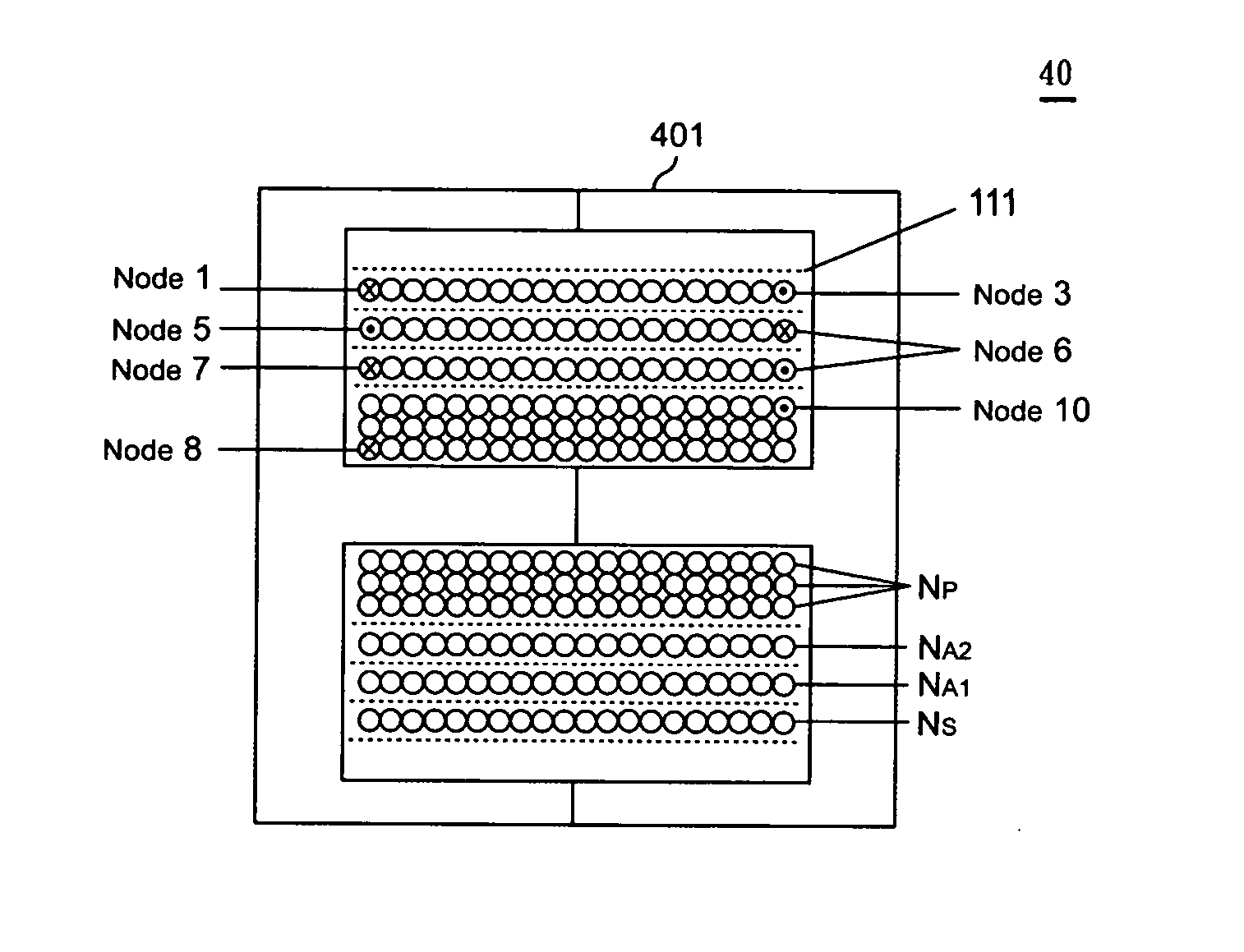
[0016]FIG. 3 shows the schematic circuit of an energy transfer apparatus for reducing conductivity electromagnetic interference for a power supply according to the present invention. The energy transfer apparatus 40 comprises a core 401. An input winding NP (between Node 8 and Node 10) wound around the core 401, an output winding Ns (between Node 1 and Node 3) wound around the core 401, and the output winding NS is capacitively coupled to the input winding NP. A supply voltage VDD is coupled to a controller U1 for providing an operating voltage. A shielding winding NA1 (between Node 6 and Node 5) wound around the core 401, and the shielding winding NA1 is electrically coupled to the input winding NP and capacitively coupled to the output winding NS. An electric potential is produced by the capacitive coupling between the shielding winding NA1, and the output winding NS for reducing potential difference between the input winding NP and the output winding NS for stabilizing an electri...


PUM


Abstract

An energy transfer apparatus is developed for reducing a conductivity electromagnetic interference and manufacturing method. The energy transfer apparatus comprises a core, an input winding, an output winding, a supply voltage and a supply winding. The supply winding includes a shielding winding and an auxiliary winding. The input winding receives an input voltage for outputting the output voltage through the core and the output winding. The shielding winding and the auxiliary winding generate the supply voltage through the core. By setting of wire size and winding turns of the shielding winding, the conductivity electromagnetic interference is reduced for stabilizing an electric potential between an input-grounding terminal and an output-grounding terminal of the energy transfer apparatus.

Description

BACKGROUND OF THE INVENTION [0001] 1. Field of the Invention [0002] The present invention relates to an energy transfer apparatus, and more particularly to an energy transfer apparatus for reducing conductivity electromagnetic interference and a manufacturing method thereof. [0003] 2. Description of Related Art [0004] In the PWM technique, much attention is paid to the influence of conductivity electromagnetic interference produced by switching a switch device with a high frequency on electronic devices. In the field of power supply, the conductivity electromagnetic interference can be lowered to meet the requirements of different international safety certifications. [0005]FIG. 1 shows a prior art circuit of a power supply, an input winding NP of the power supply 1 receives an input voltage VIN through an energy transfer apparatus 10. When a controller U1 controls the switching of a switching device Q1, the input terminal of the power supply 1 transmits the stored energy to an outpu...

Claims


Application Information

Patent Timeline
IPC IPC(8): H01F27/24
CPCH01F17/043H01F27/323H02M3/28H01F29/14H01F27/38
Inventor CHEN, CHIEN-LIANG
Owner SEMICON COMPONENTS IND LLC
Why Eureka
Try Eureka