
Surface plasmon resonance detector

a surface plasmon and detector technology, applied in the field of surface plasmon resonance detectors, can solve the problems of low vibration tolerance of spr detectors, light will not reach optical detectors, and the size of this kind of spr detectors is huge, so as to achieve the effect of simple operation, reduced volume of spr detectors of the present invention, and increased portability

Inactive Publication Date: 2007-07-05
FORWARD ELECTRONICS CO LTD
View PDF3 Cites 37 Cited by
  • Summary
  • Abstract
  • Description
  • Claims
  • Application Information

AI Technical Summary

Benefits of technology

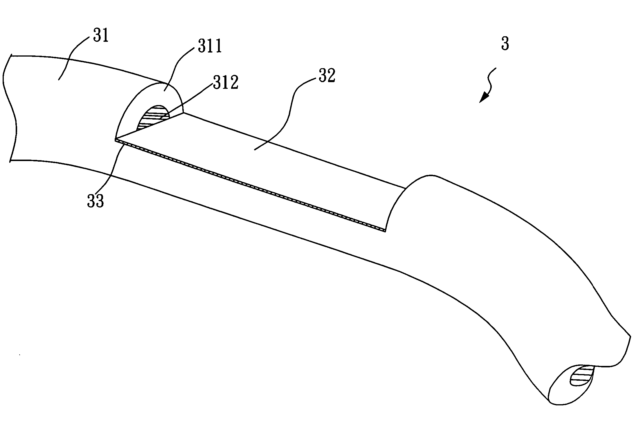
[0010] Thus, because the SPR detector of the present invention transmits optical signals between the light source, the optical-fiber biosensor unit, and the optical detector, instead of transmitting the optical signals in the atmosphere, the SPR detector of the present invention is able to sustain certain intensity of impacts without damaging the stability of the light path thereof, the volume of the SPR detector of the present invention can be further reduced, and the portability thereof can be further increased. In addition, the optical-fiber biosensor unit of the SPR detector of the present invention is connected with two the multi-mode optical fibers, which connects with the light source and the optical detector through two optical fiber connectors. As a result, when detecting bimolecular samples with the SPR detector of the present invention, there is no need to cease the operation of the SPR detector to change the light path thereof. Instead, a replacement of different optical-fiber biosensor is required. Consequently, the SPR detector of the present invention is not only simple to operate, but also able to accomplish the entire detection process rapidly and accurately.

Problems solved by technology

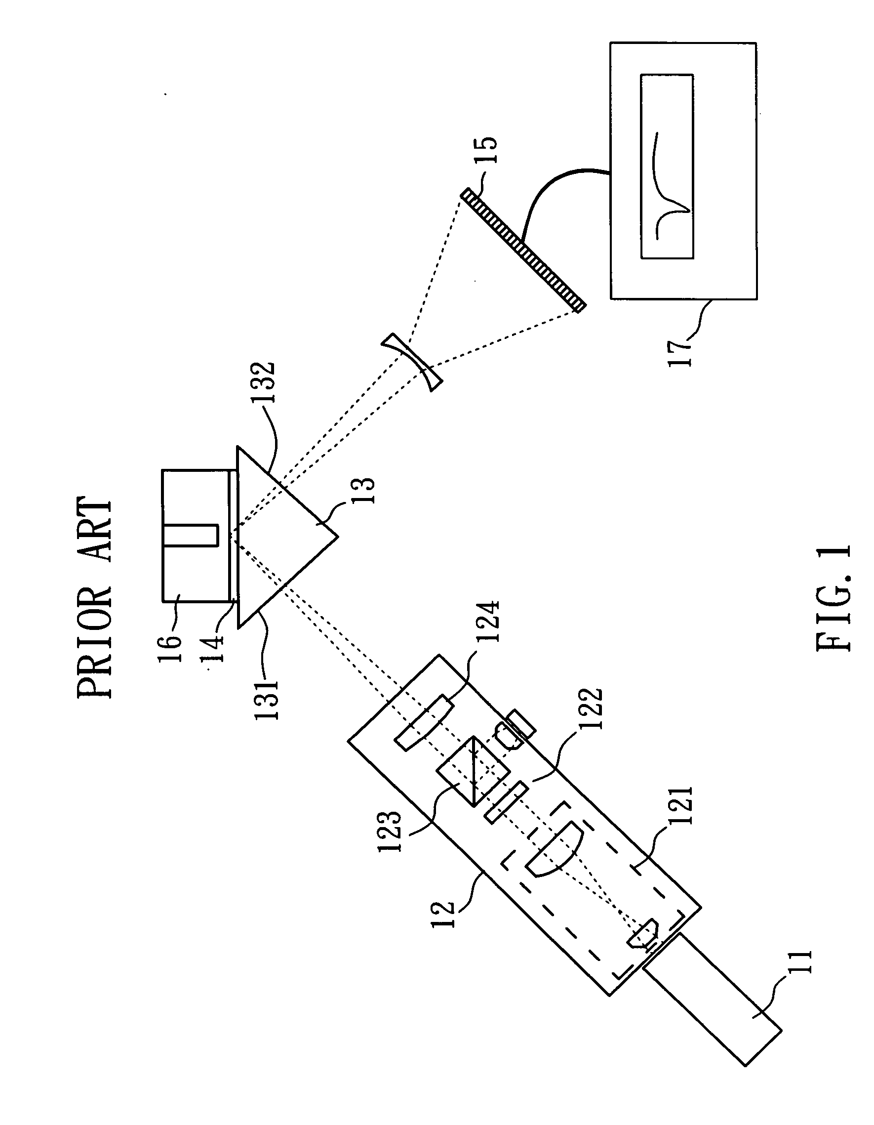
However, the size of this kind of SPR detector is huge, and the locations of the components relative to each other must be maintained accurately, or the light emitting from the incidence light treatment unit will not be correctly reflected by the metal layer formed on the back surface of the prism, and the light will not reach the optical detector.
Therefore, the SPR detectors have low tolerance to vibrations and are easily damaged by collision, rendering it inappropriate for bringing to the impacted sites by the responding staff.

Method used


Image

  • Surface plasmon resonance detector
  • Surface plasmon resonance detector
  • Surface plasmon resonance detector

Examples


Embodiment Construction

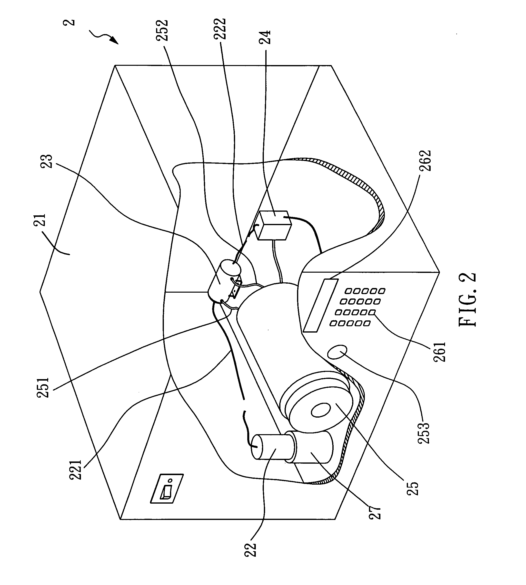
[0022]FIG. 2 is a schematic illustration showing the SPR detector of the first preferred embodiment of the present invention. The SPR detector 2 has an outer casing 21, a laser diode 22, a flow well 23, an optical diode detector 24, a solution-loading well 25, a calculation control unit (not shown), and a power supply unit 27, wherein the laser diode 22 provides the laser required for the detection to the flow well 23 through the multi-module optical fiber 221, and the laser light then passing through the detection target in the flow well 23. The laser light carrying the information related to the detection target is then transmitted through another multi-module optical fiber to the optical diode detector 24. Then, the laser light is correspondingly converted to a corresponding electric signal by the optical diode detector 24. The corresponding electric signal is then transmitted to the calculation control unit (not shown), so as to proceed with further calculation. The calculation ...


PUM


Abstract

The present invention relates to a surface plasmon resonance detector, that is portable and easy to operate, and its optical-fiber biosensor unit can be readily replaced. The SPR detector of the present invention comprises: a light source; an optical-fiber biosensor unit having a well, a coating layer, and a core layer; an optical detector; a plurality of optical fibers connecting with the light source, the optical-fiber biosensor unit and the optical detector; and a calculation and display unit connecting with the optical detector, wherein the optical detector receives the optical signals from the optical detector and display the calculation results thereof. Besides, the SPR detector of the present invention has high sensitivity and is able to identify species of trace biomolecules.

Description

BACKGROUND OF THE INVENTION [0001] 1. Field of the Invention [0002] The present invention relates to a surface plasmon resonance detector and, more particularly, to a surface plasmon resonance detector that is portable and easy to operate, while it is easy to change the biosensor unit thereof. [0003] 2. Description of Related Art [0004] For applications in medical and environmental detection, it is essential to identify the species and concentrations of the biomolecules rapidly and accurately. Such as in environmentally hazardous occasions, the responding staff must first identify the species and the concentrations of the harmful materials at the site, so as to decide the subsequent procedures of treatment according to the detection results and minimize the risks of the treatment. Thus, accuracy, sensitivity, simplicity in operation procedures and portability are important. [0005] To date, Surface Plasmon Resonance (SPR) detectors based on surface plasmon resonance effects have been...

Claims


Application Information

Patent Timeline
IPC IPC(8): G01N21/55G01N21/01G01N21/05G01N21/27G01N21/41
CPCG01N21/553G01N2021/7783G01N21/7703
Inventor TSAO, YU-CHIATSAI, WOO-HULIN, HONG-YUCHANG, JUNG-CHIEN
Owner FORWARD ELECTRONICS CO LTD
Learn More