Electrostatic ultrasonic transducer drive control method, electrostatic ultrasonic transducer, ultrasonic speaker using the same, audio signal reproduction method, ultra-directional acoustic system, and display device

a technology of electrostatic ultrasonic transducers and drive control methods, applied in the direction of transducers, piezoelectric/electrostrictive transducers, loudspeakers, etc., can solve the problems of difficult to achieve electrostatic ultrasonic transducers, difficult to perform faithful reproduction (demodulation) in such a wide band, etc., to improve electro-acoustic energy conversion efficiency

Inactive Publication Date: 2007-07-05
SEIKO EPSON CORP
View PDF2 Cites 34 Cited by
  • Summary
  • Abstract
  • Description
  • Claims
  • Application Information

AI Technical Summary

Benefits of technology

[0031] The present invention is made in view of such circumstances, and has an object of providing a Push-Pull-type of electrostatic ultrasonic transducer capable of generating a higher intensity ultrasonic wave in the same driving conditions and for intending to improve the electro-acoustic energy conversion efficiency.

Problems solved by technology

However, as shown in FIG. 17, the maximum value of the sound pressure, of the resonance-type ultrasonic transducer is 130 dB or more whereas that of the electrostatic ultrasonic transducer is as low as 120 dB, which is slightly insufficient for utilizing the transducer as an ultrasonic speaker.
Although the ultrasonic sound pressure no lower than 120 dB is required in order for sufficiently exerting the parametric effect described above, it is difficult for electrostatic ultrasonic transducers to achieve this numerical value, and accordingly, ceramic piezoelectric elements such as PZT or polymer piezoelectric elements such as PVDF have been mainly used as ultrasonic emitters.
It will be easily understood that it is difficult to perform faithful reproduction (demodulation) in such a wide band as 20 kHz by the resonance-type ultrasonic speakers using the piezoelectric elements of the related art.
In fact, in the ultrasonic speakers using the resonance-type ultrasonic transducers of the related art, the following problems have arisen.
The narrow frequency band degrades the reproduced sound quality.
If the input voltage is raised (the volume is turned up), the vibration of the piezoelectric element becomes unstable to cause the sound to get distorted, and with further raised voltage, the piezoelectric element itself might be damaged easily.
It is difficult to be formed as an array, with a large scale, or with a small size, and accordingly, the cost thereof is high.
In contrast, the ultrasonic speakers using the electrostatic ultrasonic transducers (Pull-type) shown in FIG. 16 can solve almost all problems the above technology of the related art has, but in turn has a problem that the absolute sound pressure is not sufficient for obtaining a sufficient sound volume of the demodulated sound although the wide band can be covered.
Further, since in the Pull-type ultrasonic transducers, the electrostatic force acts only in the direction for pulling the vibration films towards the fixed electrode side, and accordingly, the symmetric property in vibration of the vibration films (corresponding to the upper electrode 132 in FIG. 16) is not maintained, in the case in which the ultrasonic transducers are used for the ultrasonic speakers, there is a problem that the vibration of the vibration films directly cause audible sound.
However, since the Push-Pull type ultrasonic transducer has the through holes, through which the sound passes, with the relatively small areas, it is problematically difficult for the Push-Pull-type ultrasonic transducer as it is to generate sufficient sound pressure in the air.

Method used


Image

  • Electrostatic ultrasonic transducer drive control method, electrostatic ultrasonic transducer, ultrasonic speaker using the same, audio signal reproduction method, ultra-directional acoustic system, and display device
  • Electrostatic ultrasonic transducer drive control method, electrostatic ultrasonic transducer, ultrasonic speaker using the same, audio signal reproduction method, ultra-directional acoustic system, and display device
  • Electrostatic ultrasonic transducer drive control method, electrostatic ultrasonic transducer, ultrasonic speaker using the same, audio signal reproduction method, ultra-directional acoustic system, and display device

Examples


first embodiment

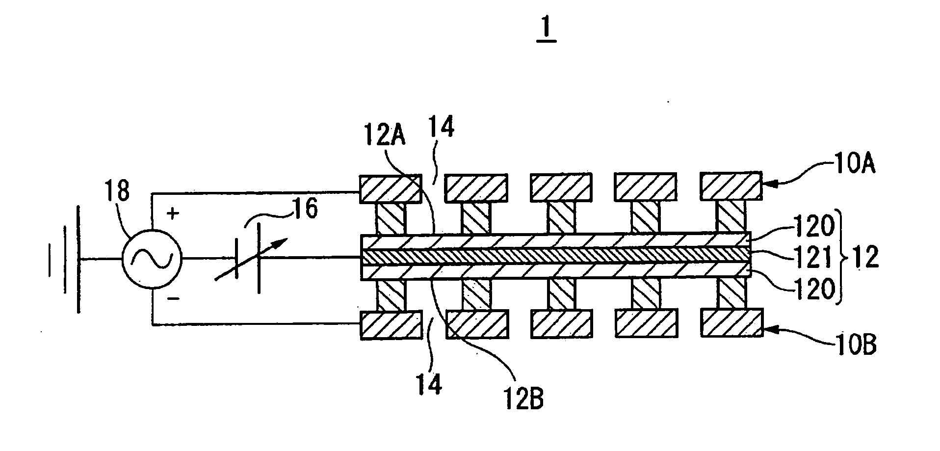
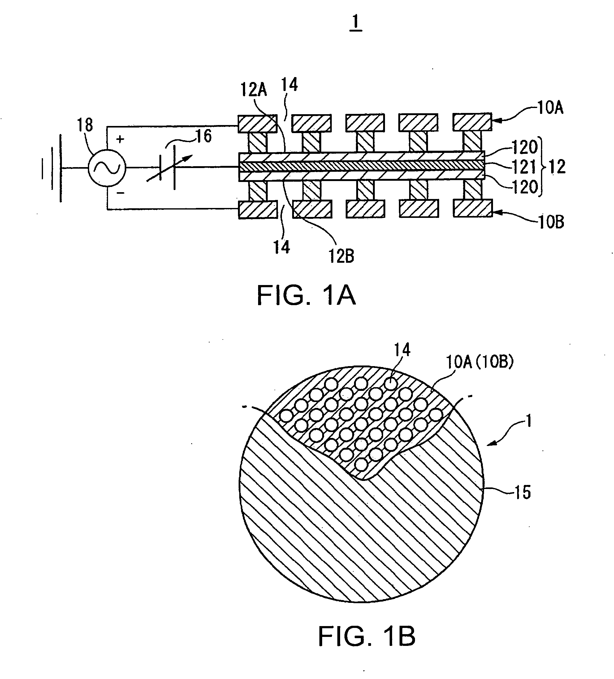
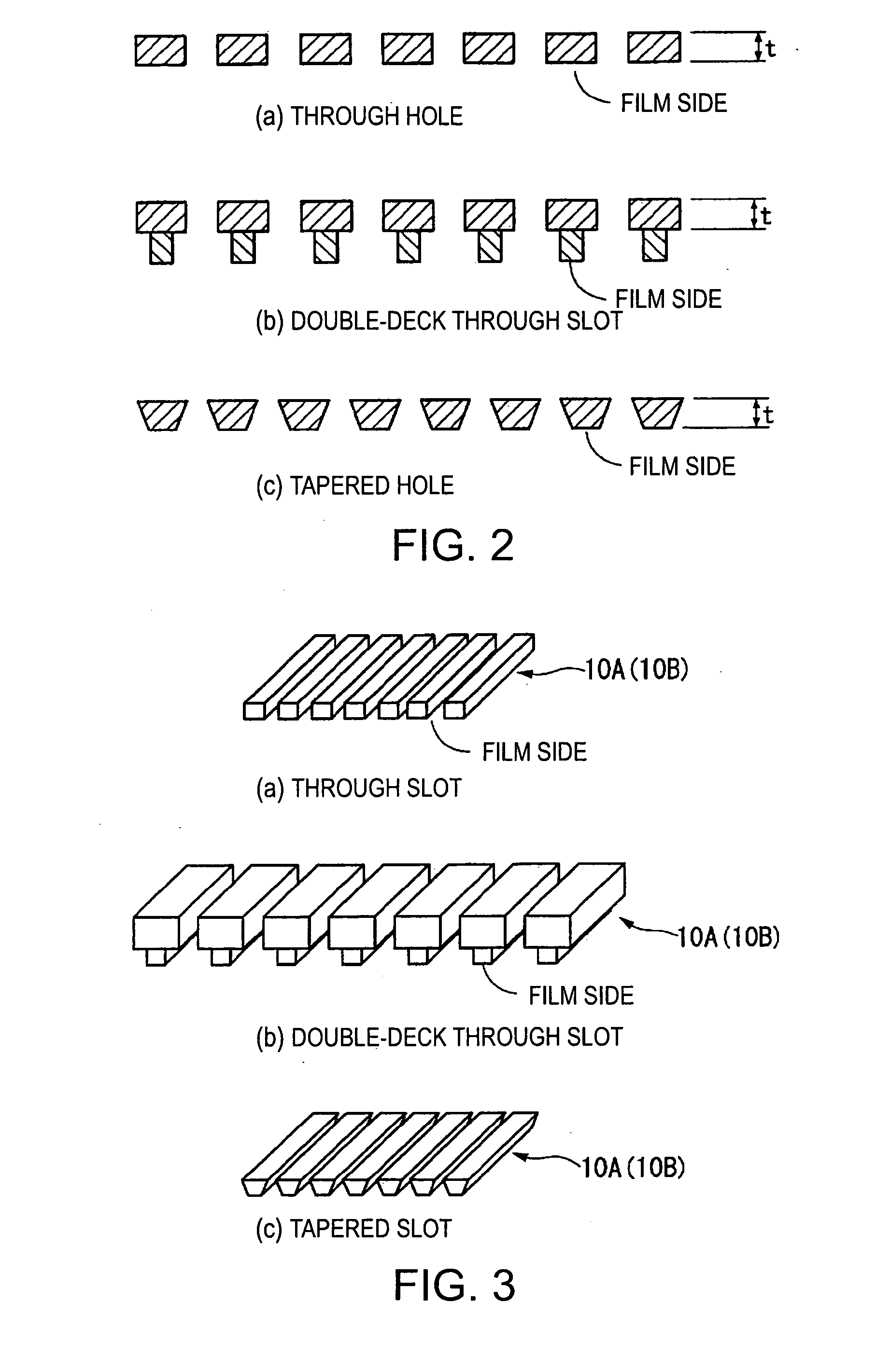
[0181] In one embodiment (the first embodiment) of the invention, assuming, for example, that λ is the wavelength of the carrier wave having a frequency shifted as a predetermined amount of frequency from the resonance frequency, which becomes the mechanical resonance frequency of the vibration film 12 in the electrostatic ultrasonic transducer 1, it is configured that the thickness t of each of the pair of electrodes 10A, 10B becomes (λ / 4)·n or roughly (λ / 4)·n (where, λ is the wavelength of the ultrasonic wave, n is a positive odd number).

[0182] In the electrostatic ultrasonic transducer according to the invention composed of the above configuration, the plurality of through holes 14 is provided to the first electrode 10A and the second electrode 10B at positions where the first electrode 10A and the second electrode 10B face each other, and the alternating-current signal, which is the drive signal, is applied to the pair of electrodes composed of the first and the second electrode...

second embodiment

[0203] Now, a configuration of an ultrasonic transducer according to another embodiment of the invention will be shown in FIG. 9. The configuration of the ultrasonic transducer 55 according to the invention is the same as the configuration shown in FIG. 1 except that a sound reflecting plate is disposed on the rear face of the ultrasonic transducer. Specifically, the ultrasonic transducer 55 according to the present embodiment is a ultrasonic transducer provided with a pair of electrodes 10A, 10B each including conductive member formed of a conductive material which functions as an electrode, a vibration film 12 held between the pair of electrodes 10A, 10B, and including the conductive layer 121 to which a direct-current bias voltage is applied, and a member (not shown) for holding the pair of electrodes 10A, 10B, and the vibration film 12, the pair of electrodes 10A, 10B having the same and plural number of holes at positions opposing across the vibration film 12, and a alternating...


PUM


Abstract

A Push-Pull-type electrostatic ultrasonic transducer includes a first electrode having a through hole, a second electrode having a through hole making a pair with the through hole of the first electrode, and a vibration film held between a pair of electrodes composed of the first and the second electrodes and having a conductive layer to which a direct-current bias voltage is applied, and holds the pair of electrodes and the vibration film. Assuming that λ is the wavelength of the carrier wave having a frequency shifted as a predetermined amount of frequency from the resonance frequency, which is the mechanical resonance frequency of the vibration film, the thickness t of each of the pair of electrodes is set to (λ / 4)·n or roughly (λ / 4)·n (where, λ is the wavelength of the ultrasonic wave, n is a positive odd number), and an alternating-current signal, which is a modulated wave obtained by modulating the carrier wave in the ultrasonic frequency band with a signal wave in an audible frequency band, is applied between the pair of electrodes.

Description

BACKGROUND OF THE INVENTION [0001] 1. Field of the Invention [0002] The present invention relates to an electrostatic ultrasonic transducer drive control method, an electrostatic ultrasonic transducer, an ultrasonic speaker using the same, an audio signal reproduction method, an ultra-directional acoustic system, and a display device capable of generating constant high sound pressure throughout a broad frequency range. [0003] The present invention claims priority based on Japanese Patent Applications JP 2005-364371 filed on Dec. 19, 2005, and JP 2006-318700 filed Nov. 27, 2006, the contents of which being incorporated herein by reference. [0004] 2. Background Art [0005] In the past, most ultrasonic transducers have been of resonance type using piezoelectric ceramic. [0006] Here, FIG. 15 shows a configuration of such an ultrasonic transducer in the past. In the past, most ultrasonic transducers have been of resonance-type using piezoelectric ceramic as a vibrator element. The ultraso...

Claims


Application Information

Patent Timeline
Patent Type & Authority Applications(United States)
IPC IPC(8): H04R3/00H04B3/00
CPCH04R1/06H04R1/403H04R2430/20H04R2201/401H04R2217/03H04R17/00
Inventor MATSUZAWA, KINYA
Owner SEIKO EPSON CORP
Why Eureka
Try Eureka