System & method for the design, creation and installation of implant-supported dental prostheses

a dental prosthesis and implant technology, applied in the field of system & method for the design, creation and installation of implant-supported dental prostheses, can solve the problems of unsatisfactory information revealed by conventional two-dimensional x-ray images, unaided manual preparation of the jaw for implants, and the inability to serve as a platform for traditional dental prosthetics. achieve the effect of fast delivery of implant services to a patien

Active Publication Date: 2007-07-05
HALL BENSON LUTHER
View PDF17 Cites 60 Cited by
  • Summary
  • Abstract
  • Description
  • Claims
  • Application Information

AI Technical Summary

Benefits of technology

[0054] Another aspect of the present invention is that it enables dentists to earn additional income.
[0055] Another aspect of the present invention is that it pro

Problems solved by technology

In particular, there are some patients whose teeth are no longer present, or whose teeth have deteriorated to the degree that they cannot serve as a platform for the mounting of traditional dental prosthetics, e.g. bridges.
This information is, however, not fully revealed by conventional two-dimensional x-ray images.
Unaided manual preparation of a jaw for implants is challenging, especially if done infrequently by a practitioner, because of the difficulty in estimating positions and angles accurately by eye, within a deep hole of small diameter in a patient's mouth.
Even if the work is being done by an experienced dentist or oral surgeon, chances for location or orientation errors are great.
The physical molds after being shipped to a dental laboratory are used to build up a prosthesis, in a traditional highly labor-intensive process demanding high skill level and long experience for good results.
One group of limitations of prior-art procedures are those associated with unaided manual preparation of the mouth for, and placement of, dental implants: a) The human jawbone is highly variable in thickness from location to location, and varies from person to person.
If the hole in the bone is drilled at an incorrect location and/or angle, the tip of the implant may pass through the bone and out the far side, weakening its attachment strength.
Protruding implant tips also raise patient objections on cosme

Method used


Image

  • System & method for the design, creation and installation of implant-supported dental prostheses
  • System & method for the design, creation and installation of implant-supported dental prostheses
  • System & method for the design, creation and installation of implant-supported dental prostheses

Examples


Embodiment Construction

[0117] The present invention will now be described in detail with reference to a few preferred embodiments thereof as illustrated in the accompanying drawings. In the following description, numerous specific details are set forth in order to provide a thorough understanding of the present invention. It will be apparent, however, to one skilled in the art, that the present invention may be practiced without some or all of these specific details. In other instances, well known operations have not been described in detail so not to unnecessarily obscure the present invention.

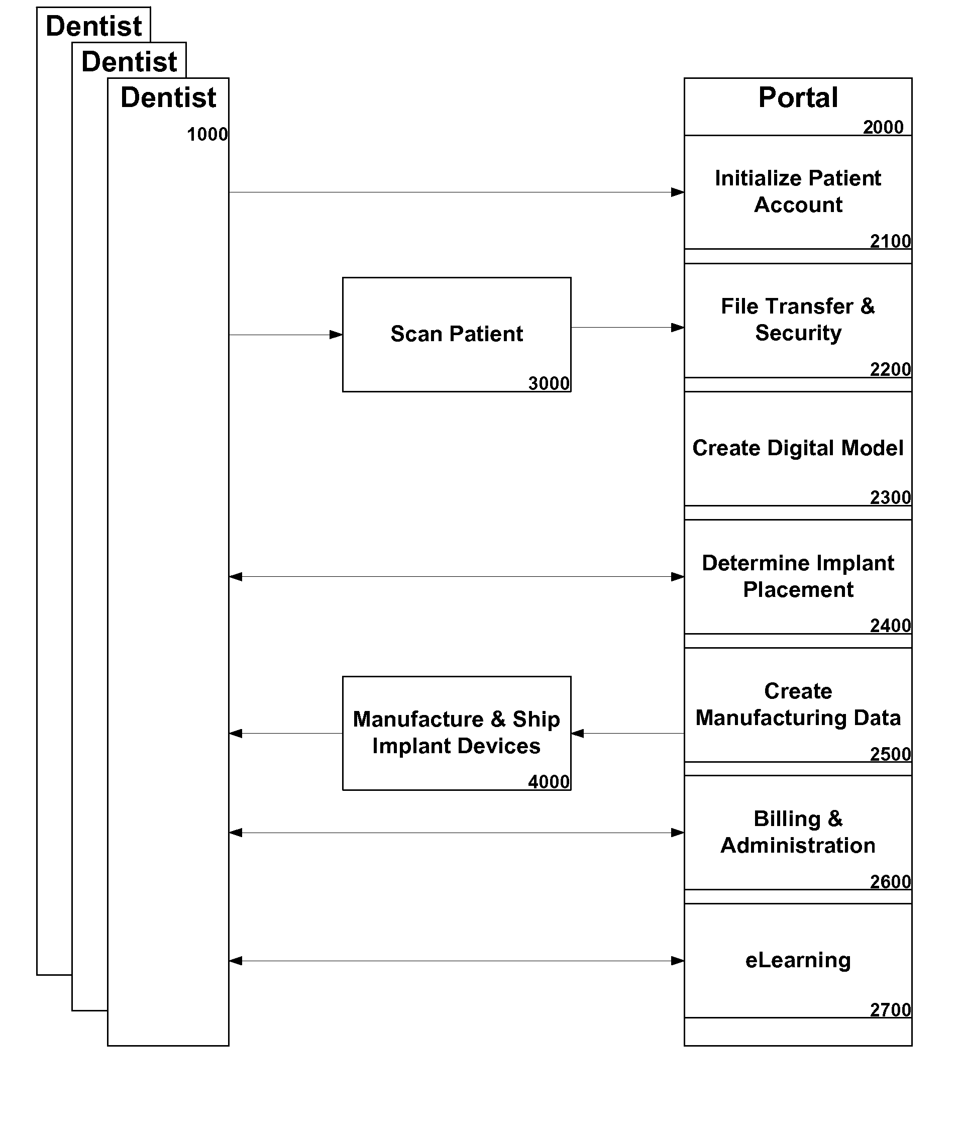
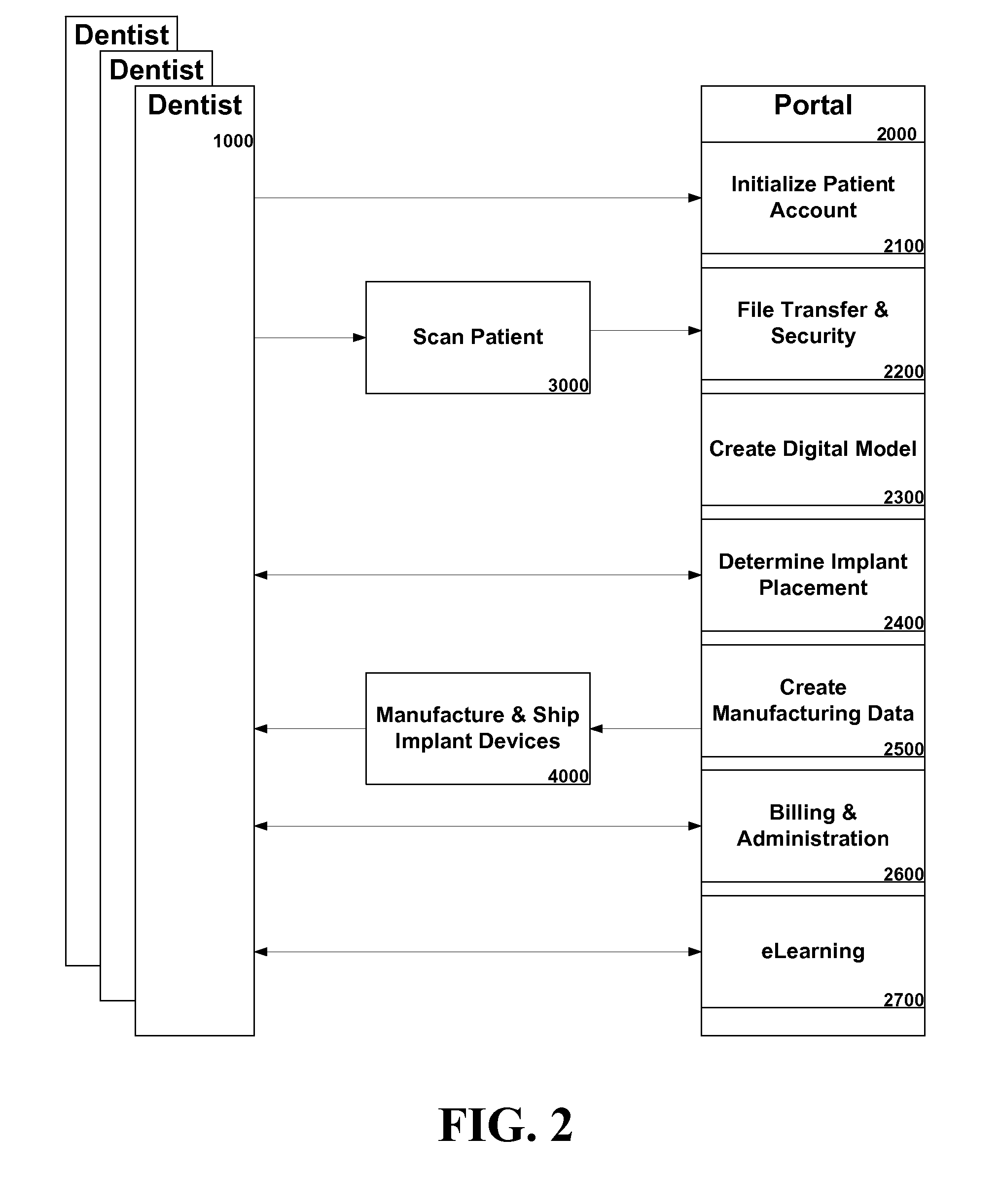
[0118] Referring now to FIG. 1, the relationship between a portal 2000 and a dentist 1000 is illustrated for an embodiment of the present invention. A dentist 1000 refers a patient to a scanning center after diagnosing and recommending an implant procedure. An initialize patient account 2100 module is used by the dentist to establish a secure account for the patient. At the scan patient 3000 portion of the process...


PUM


Abstract

An improved system and method for the design, creation and installation of implant-supported dental prostheses is provided. A network accessible portal facilitates communication among a dental professional, a scanning center, a manufacturing center and others in the design and production of a dental drill guide and prosthesis, utilizing cone beam imaging, a rotatable 3-dimension representation of a patient's jaw, virtual placement of one or more implants and virtual testing prior to manufacture. Dental professionals may access the portal on a subscription or non-subscription basis.

Description

[0001] Claim is hereby made for the benefit of U.S. Provisional Application No. 60 / 738,516 filed Nov. 22, 2005, and U.S. Provisional Application No. 60 / 828,064, filed Oct. 3, 2006, incorporated herein in their entirety by reference.FIELD OF THE INVENTION [0002] The present invention relates to the field of systems & methods for the design, creation and installation of implant-supported dental prosthesis. BACKGROUND OF THE INVENTION [0003] It is well known in the art that some dental patients require restoration of teeth. In particular, there are some patients whose teeth are no longer present, or whose teeth have deteriorated to the degree that they cannot serve as a platform for the mounting of traditional dental prosthetics, e.g. bridges. [0004] Implants, now in use for about forty years, are the standard way to attach fixed dental prostheses in place. One implant may support a single replacement tooth, usually cemented atop an abutment. Where several teeth are missing, two or mor...

Claims


Application Information

Patent Timeline
IPC IPC(8): A61C11/00
CPCA61C13/0004A61C1/084G16H20/40
Inventor HALL, BENSON LUTHER
Owner HALL BENSON LUTHER
Why Eureka
Try Eureka