Method of frequency planning in an ultra wide band system

Inactive Publication Date: 2007-07-05
WINONICS RES
View PDF1 Cites 27 Cited by
  • Summary
  • Abstract
  • Description
  • Claims
  • Application Information

AI Technical Summary

Benefits of technology

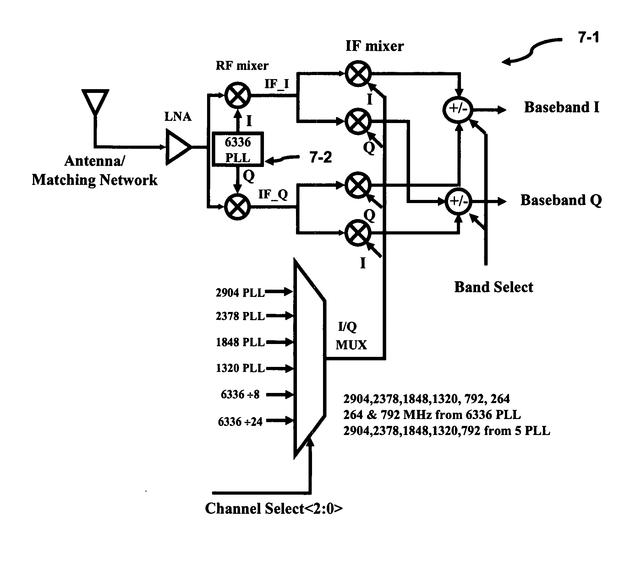
[0016] The present invention provides for a simpler technique to extract the signal from a multi-channel communication system. This technique reduces the number of required reference oscillators or synthesizers thereby reducing the area and power concerns of the architecture and is know as frequency planning. The highest frequency of operation

Problems solved by technology

The higher the channel frequency then there is a possibility for more quadrature mismatch, for instance, the I and Q signals may not be 90° out of phase with each other.
In addition, carrier leakage may occur in the mixers degrading the recovered signal, and finally the receiver may suffer an output dc offset.
Finally, in order to meet the 9.47 nS switching time that was mentioned earlier, the synthesizer requires that all 14 PLLs are in continuous operation which will cause high power dissipation levels.
At 10 GHz, it may be difficult for the synthesizer feedback divider to fully function over PVT (Process, voltage

Method used


Image

  • Method of frequency planning in an ultra wide band system
  • Method of frequency planning in an ultra wide band system
  • Method of frequency planning in an ultra wide band system

Examples


case 2

[0078] A WLAN Interference Signal

[0079] In PAN applications, besides a UWB interfering signal, WLAN devices (e.g., 802.11) can create an undesired interference signals. The WLAN output power levels can be as high as 20 dBm within a bandwidth of 20 MHz. This high power level will cause the UWB receiver system to fail if the WLAN transmitter is 1 m away and the WLAN signal falls right on top of either image or signal channel. The WLAN signal desensitizes the LNA and mixer stages, which can become fully saturated. Therefore, the UWB receiver needs to be cleaver enough to avoid the WLAN interference signal or increase the linearity of the LNA and mixer. Usually, the linearity can not be achieved without a compromising effect such as designing a more power dissipative circuit or using more silicon area. Both of these design issue constraints can be costly. Another approach to avoid a WLAN interference signal is preferred.

[0080] A Wireless LAN Avoidance Scheme

[0081] One possibility is ...


PUM


Abstract

The present invention provides reduces the number of required synthesizers thereby reducing the area and power concerns to extract/insert a signal from/to a multi-channel communication system and is also known as frequency planning. The highest frequency of operation required for the synthesizers or oscillators is approximately the midpoint of the entire signal frequency range. Two superimposed Weaver architectures are used to form the architecture. The receiver extracts the baseband I and Q signals from the multi-channel communication system, while the transmitter upconverts the baseband I and Q signals to the multi-channel communication system. The Weaver architecture, depending on the select bit, can enhance the image signal and reduce the desired signal or the image signal can be reduced while the desired signal is enhanced. Because the image and signal components are symmetrically displaced from the RF LO, less IF LO frequencies or synthesizers are required to operate the system.

Description

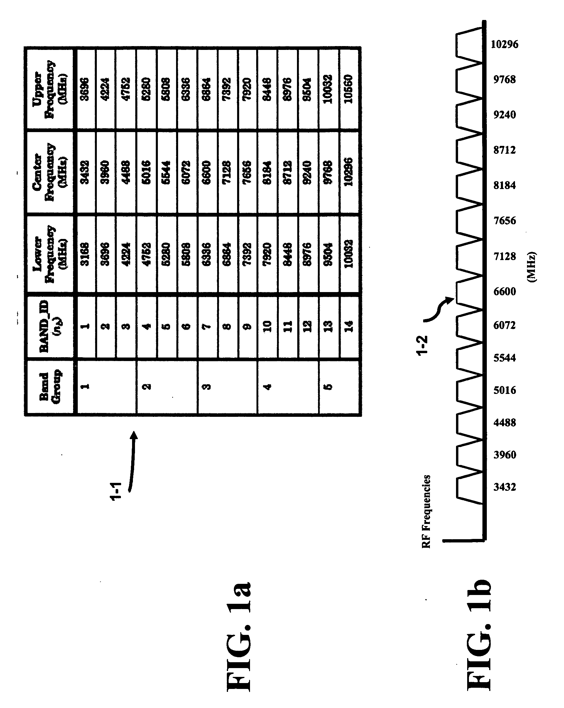
CROSS-REFERENCE TO RELATED APPLICATIONS [0001] The present application is related to the co-filed U.S. application entitled “APPARATUS AND METHOD FOR ULTRA WIDE BAND ARCHITECTURES” filed on Dec. 29, 2005, which are all invented by at least one common inventor as well as being assigned to the same entity as the present application and incorporated herein by reference in their entireties. BACKGROUND OF THE INVENTION [0002] Ultrawideband (UWB) wireless technology is a high data rate (480+ Mbps), short range (up to 20 meters), and low power technology that promises to eliminate confusing cables and wires between interfaces. A de facto standard has emerged and is known as the MultiBand OFDM Alliance (MBOA). The FCC (Federal Communication Commission) has allocated an unlicensed radio spectrum from 3.2 GHz to 10.6 GHz for the MBOA-UWB technology. [0003] The full bandwidth of 7.5 GHz is broken up into fourteen multiple carriers each having a 525 MHz bandwidth and in essence forming a multi-...

Claims


Application Information

Patent Timeline
IPC IPC(8): H03J7/32
CPCH03J1/0008H03D7/165
Inventor RAZAVI, BEHZADSOE, ZAW
Owner WINONICS RES
Why Eureka
Try Eureka