
Method of improving the properties of a repaired component and a component improved thereby

a technology of fatigue performance and mechanical properties, which is applied in the direction of mechanical equipment, machines/engines, manufacturing tools, etc., can solve the problems of fatigue cracks in the areas of components subject to high operational stresses, components susceptible to high cycle fatigue (hcf) components susceptible to high cycle fatigue and other stress related failures, so as to improve material and mechanical properties, and improve the effect of material and mechanical properties

Inactive Publication Date: 2007-07-12
PREVEY PAUL S
View PDF14 Cites 47 Cited by
  • Summary
  • Abstract
  • Description
  • Claims
  • Application Information

AI Technical Summary

Benefits of technology

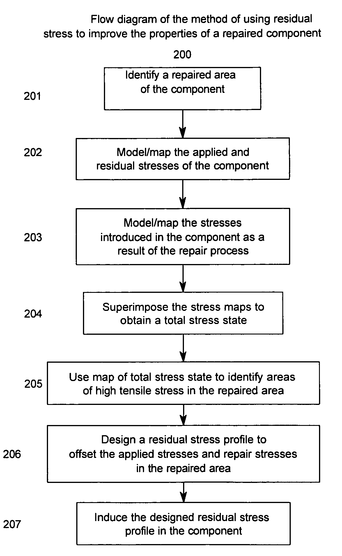
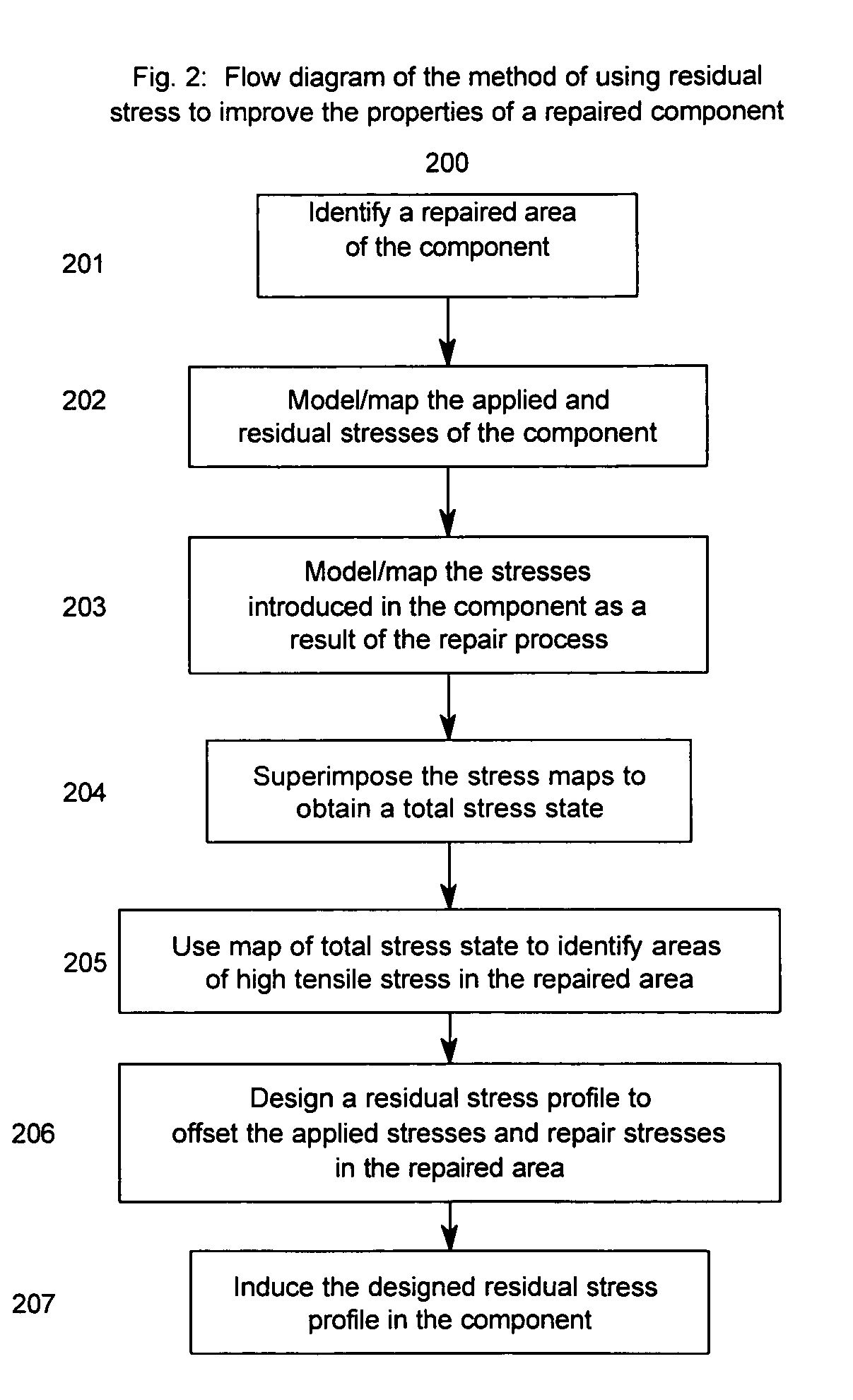
"The present invention provides a method for improving the fatigue performance, foreign object damage tolerance, and resistance to stress related failure mechanisms of repaired components subject to high applied stresses. The method involves identifying an area of a repaired component, determining the residual stresses introduced during the repair operation, and inducing a compressive residual stress distribution to offset the residual stresses. The compressive residual stress can be induced by burnishing or other methods. The repaired area can be the entire repaired area or a portion of it. The compressive residual stress can extend through the thickness of the component. This method reduces operation and maintenance costs for equipment subject to high operational stresses and provides an efficient and cost-effective way to restore the material and mechanical properties of a repaired component. It also eliminates the need for a heat treatment after repair and provides an easily implemented method for restoring the material and mechanical properties of a repaired component."

Problems solved by technology

The high vibratory and tensile stresses experienced by various moving or rotating components, such as those found in rotating turbo machinery in operation (particularly the blading members of the fan, compressor, and turbine stages in gas turbine engines), make such components susceptible to high cycle fatigue (HCF) and other stress related failure mechanisms such as stress corrosion cracking (SCC).
HCF and SCC ultimately limit the service life of these components as prolonged exposure to such extreme operating conditions leads to the development of fatigue cracks in areas of the component subject to high operational stresses.
The fatigue life of a component can be further limited by outside forces such as by the occurrence of foreign object damage (FOD).
FOD, such as encountered by turbo machinery, especially along the leading and trailing edges of blading members, significantly reduces the service life of components.
The potentially catastrophic effects of HCF and FOD require that fatigue-life limited components be monitored and periodically inspected for both cracks and FOD.
Additional damage mechanisms, such as the erosion of the tips of blading members from contact with sealing members in a turbine engine, may adversely impact the aerodynamic performance of an engine in addition to serving as an initiation site for fatigue cracks.
This type of damage may also necessitate the removal and repair or replacement of the component.
The inspection of components and the retirement of components from service adversely impact operation time and equipment cost, such as the flight readiness and maintenance costs, of the aircraft in which the components are employed.
However, each of these alternatives is extremely expensive.
While these methodologies may return a component to its original, pre-damage dimensions, they do not necessarily restore the desired material properties to the component, particularly in the repaired areas.
As disclosed in U.S. Pat. No. 6,568,077, repair operations such as machining or welding may actually further degrade the material properties in areas adjacent to the repaired area by the introduction of undesirable tensile residual stresses and thermal effects thereby increasing the likelihood of failure in and around the repaired area.
However, heat treatments can be difficult to employ and may result in component distortion and other undesirable effects such as the formation of oxides in some titanium alloys.
Each of these conditions limits the applicability of the disclosed repair techniques.
This, in turn, decreases operation and maintenance costs and, such as for aerospace components, may increase the flight readiness of the aircraft in which the component is employed.
Despite the demonstrated beneficial effects, LSP processing is expensive, labor intensive, and has a low rate of production as multiple treatments and operations are necessary to completely treat a given area.
While the use of welding and brazing techniques to repair turbine engine components is known in the art, such techniques have not been used to repair areas subject to high-applied stress due to the inherent weakness of material introduced in the repair and the degradation of material surrounding the repair.
Further, known techniques for improving the material properties of a repaired component are expensive, labor intensive, and time consuming.
These drawbacks often offset or eliminate any economic benefits gained by repairing rather than replacing damaged components.

Method used


Image

  • Method of improving the properties of a repaired component and a component improved thereby
  • Method of improving the properties of a repaired component and a component improved thereby
  • Method of improving the properties of a repaired component and a component improved thereby

Examples


Embodiment Construction

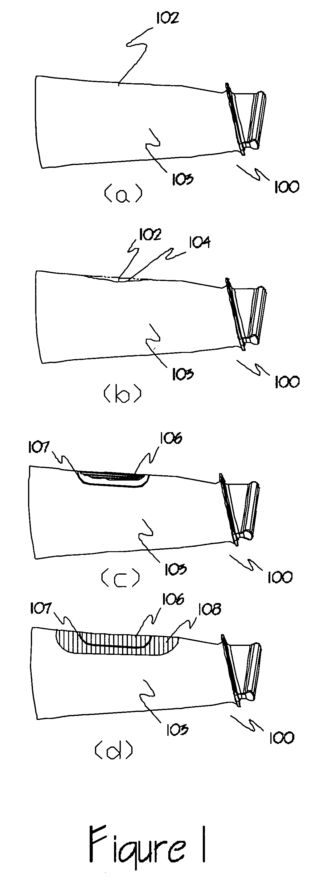
[0030]Metallic components subject to cyclic loading and high-applied stresses, such as the blading members of turbine engines, are susceptible to the development of fatigue cracks that can ultimately lead to the failure of the component. The occurrence of foreign object damage, such as along the leading and trailing edges of blading members of turbo machinery components, hastens the development of fatigue cracks as the damage locations act as stress risers or stress concentrators. Similarly, the abrasion and erosion of the tips of blading members as a result of contact with sealing members around the periphery of the engine and the erosion of blading members from contact with super-heated steam not only decreases the aerodynamic efficiency of the engine, but may also serve as initiation sites for fatigue cracks.

[0031]For an exemplary illustration, when a fatigue crack or similar damage is found in a blading member of a rotating turbo machinery component, the blading member is remove...


PUM

PropertyMeasurementUnit
areaaaaaaaaaaa
compressive stressesaaaaaaaaaa
applied stressaaaaaaaaaa

Abstract

A repaired component with improved material and mechanical properties and a method of improving the properties of a repaired component are provided. The repaired component comprises a body, a repaired area integral with the body, and an area of compressive residual stress wherein the area of compressive residual stress comprises at least a portion of the repaired area. One method for improving the fatigue performance, foreign object damage tolerance, and resistance to stress related failure mechanisms of a repaired component includes inducing a designed residual compressive stress distribution with a controlled amount of cold work in the repaired area to offset high-applied tensile stresses and stresses introduced as a result of the repair procedure as well as to improve the properties of the material added to the component during the repair.

Description

[0001]This application claims the benefit of U.S. provisional application for patent 60 / 757,231 filed Jan. 9, 2006.BACKGROUND OF THE INVENTION[0002]The present invention relates to a method for improving the fatigue performance and resistance to stress related failure mechanisms of repaired metallic components, and, more specifically, to a method of using residual compressive stresses to treat repaired components to improve fatigue performance, increase foreign object damage tolerance, and increase resistance to stress related failure mechanisms and a repaired aerospace component improved thereby.[0003]The high vibratory and tensile stresses experienced by various moving or rotating components, such as those found in rotating turbo machinery in operation (particularly the blading members of the fan, compressor, and turbine stages in gas turbine engines), make such components susceptible to high cycle fatigue (HCF) and other stress related failure mechanisms such as stress corrosion ...

Claims


Application Information

Patent Timeline
Patent Type & Authority Applications(United States)
IPC IPC(8): B23P6/00
CPCB23P6/002Y10T29/49764B23P9/02B23P9/04F01D5/005Y02T50/673F05D2230/238F05D2230/233F05D2230/30F05D2230/232F05D2230/237F05D2230/10F05D2230/90Y10T29/49771Y10T29/49718B23P9/00Y02T50/60
Inventor PREVEY, PAUL S.
Owner PREVEY PAUL S
Learn More