This helps you quickly interpret patents by identifying the three key elements:
Problems solved by technology
Method used
Benefits of technology
[0024] According further to the system described herein, a plurality of trace sample collection systems may be employed in order to increase the sampled area of target surface as well as decrease the time required to obtain said sample. An example of the use of a plurality of trace sample collection systems would be at least one vertical array of trace sample collection systems disposed to one or both sides of a walking person, said arrangement referred to as a turnstile. Another example would
Problems solved by technology
The pressure of the pressurized gas may be about one hundred pounds per square inch, a value easily obtained with small compressors, but significantly higher pressures may also be employed, and may be limited o
Method used
Image
Click on the blue label to locate the original text in one second.
Reading with bidirectional positioning of images and text.
Examples
Example
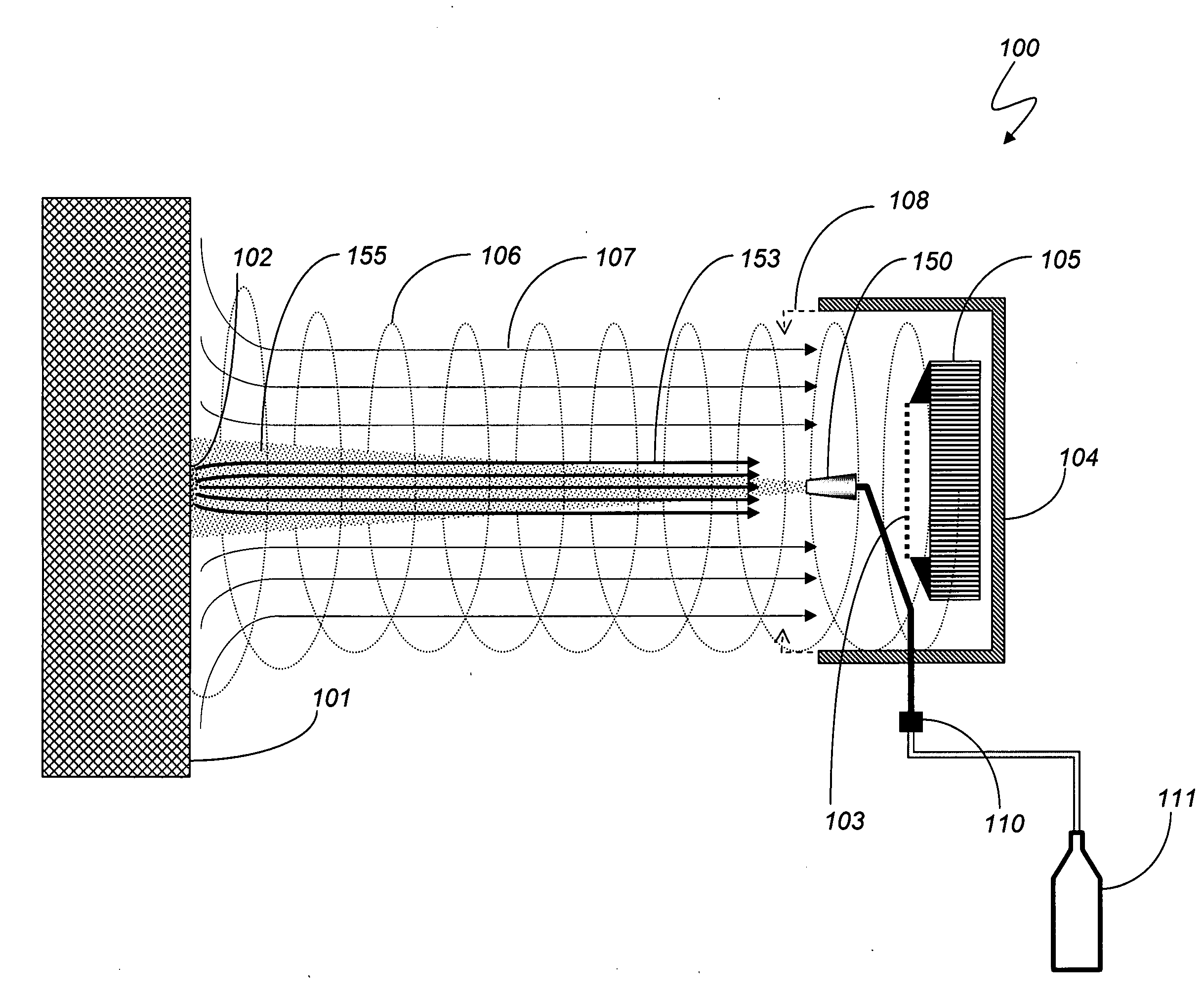
[0033] A handheld vacuum with a trace particle collection filter used in conjunction with existing wiping systems is illustrated in FIG. 1 showing basic features of non-contact particle collection system based on the existing state-of-the-art. The sample collection device 4 is brought in very close proximity to a target surface 1 that may have a trace sample of target particles 2. The vacuum pump 5 of the sample collection device 4 is activated, creating an inward flow of air 7. Sample collecting media 3 is disposed between the target surface 1 and the vacuum pump 5 such that any trace particles may be collected on or in the sample collecting media 3. The sample collecting media 3 may be a filter, such as chemical filter paper. The sample collecting media 3 is then removed from the sample collection device 4 and transported to a separate detection instrument in order to determine if trace particles of the target substance were collected. The separation distance between the sample co...
PUM
Abstract
An explosive and narcotics detection system detects the presence of trace particles of materials that are adhering to surfaces. In order to detect such particles, to the particles are first dislodged or released from the surface, then transported to the detection instrument, and then accumulated on or in a particle collection device. When the sample collecting system and the target surface are in relative motion across the line-of-sight greater than fifteen centimeters per second, non-contact sample collection may be accomplished using a vortex or vortex attractor particle collector together with a plurality of air or aerosol jets. A plurality of large diameter vortex collectors may obtain samples at relative line-of-sight velocities greater than five feet per second over a large surface area and for a complex-shaped surface.
Description
CROSS-REFERENCE TO RELATED APPLICATIONS [0001] This application is a Continuation-in-part of U.S. application Ser. No. 11 / 492,672, filed Jul. 25, 2006 (pending), which is a Continuation-in-part of U.S. Ser. No. 11 / 258,477, filed Oct. 25, 2005 (pending), and which claims priority to Provisional Application 60 / 708,017, filed Aug. 12, 2005 (expired), and which is a Continuation-in-part of U.S. Ser. No. 10 / 890,820, filed Jul. 14, 2004 (now U.S. Pat. No. 7,098,672), which is a Continuation-in-part of U.S. Ser. No. 10 / 818,434, filed Apr. 5, 2004 (now U.S. Pat. No. 6,870,155), which is a Continuation-in-part of U.S. Ser. No. 10 / 349,491, filed Jan. 22, 2003 (now U.S. Pat. No. 6,828,795), which is a Continuation-in-part of U.S. Ser. No. 10 / 295,039, filed Nov. 14, 2002 (abandoned), and which is a Continuation-in-part of U.S. Ser. No. 10 / 295,010, filed Nov. 14, 2002 (now U.S. Pat. No. 6,861,646), which claims priority from Provisional Application 60 / 363,485, filed Mar. 12, 2002 (expired), and ...
Claims
Application Information
Patent Timeline
Application Date:The date an application was filed.
Publication Date:The date a patent or application was officially published.
First Publication Date:The earliest publication date of a patent with the same application number.
Issue Date:Publication date of the patent grant document.
PCT Entry Date:The Entry date of PCT National Phase.
Estimated Expiry Date:The statutory expiry date of a patent right according to the Patent Law, and it is the longest term of protection that the patent right can achieve without the termination of the patent right due to other reasons(Term extension factor has been taken into account ).
Invalid Date:Actual expiry date is based on effective date or publication date of legal transaction data of invalid patent.