Light emitting element and lighting instrument

a technology of light-emitting elements and lighting instruments, which is applied in the direction of lighting and heating apparatus, fixed installations, discharge tubes luminescnet screens, etc., can solve the problems of not being fully solved and exhibiting deviations in color rendering properties, and achieve excellent color rendering properties and wide chromaticity ranges. , the effect of improving the light-emission efficiency

Active Publication Date: 2007-07-12
NAT INST FOR MATERIALS SCI
View PDF26 Cites 71 Cited by
  • Summary
  • Abstract
  • Description
  • Claims
  • Application Information

AI Technical Summary

Benefits of technology

[0037] The above feature resides in adoption of a fluorescent material which is configured to emit yellowish red or red light and which comprises a CaAlSiN3 crystal phase including, dissolved therein in a solid state, one kind or two or more kinds of element(s) selected from Mn, Ce, Pr, Nd, Sm, Eu, Gd, Tb, Dy, Ho, Er, Tm, Yb, and Lu, in a manner that the fluorescent material is mixed with another fluorescent material configured to emit green, yellowish green, or yellow light, and that the mixedly obtained phosphor is combined with a semiconductor light emitting element configured to emit bluish purple or blue light, thereby succeeding in fabricating a white light emitting diode for emitting white light with warmness at a high efficiency, with an extremely remarkable effect.
[0038] Further, the present invention enables arbitrary color tones by virtue of the above configuration, and thus has succeeded in fabricating and providing an intermediate color light emitting diode configured to emit intermediate color light, with an extremely remarkable significance. In this way, the present invention exhibits an exceptional effect such as achievement of a light emitting diode which has a wider chromaticity range and which is excellent in color rendering property as compared with a situation of adoption of the conventionally known red phosphor, so that the present invention is-expected to be widely utilized in various usages including decorative usage from now on in a manner to largely contribute to development of the industry through the lighting technique.
[0039] Moreover, the light emitting diode of the present invention has a higher light-emission efficiency, and it is thus expected that the same directly realizes an energy-saving lighting instrument to thereby exhibit an exceptional effect.

Problems solved by technology

However, the white light emitting diode comprising a blue light emitting diode element and a yttrium / aluminum / garnet based phosphor has a feature to emit bluish white light due to lack of a red component, thereby problematically exhibiting deviation in a color rendering property.
However, the above-described problem has not been fully solved even by the inventions proposed in them, which is away from a situation where the needs demanding diversified color schemes and chromaticities are fully dealt with, while such proposals are also insufficient in emission intensity, thereby still exhibiting a problem to be solved.
It will be thus desirable to make the same approach also in design of fluorescent material in view of the above consideration, since usage of cadmium appears to be undesirable.

Method used


Image

  • Light emitting element and lighting instrument
  • Light emitting element and lighting instrument
  • Light emitting element and lighting instrument

Examples


embodiment 1

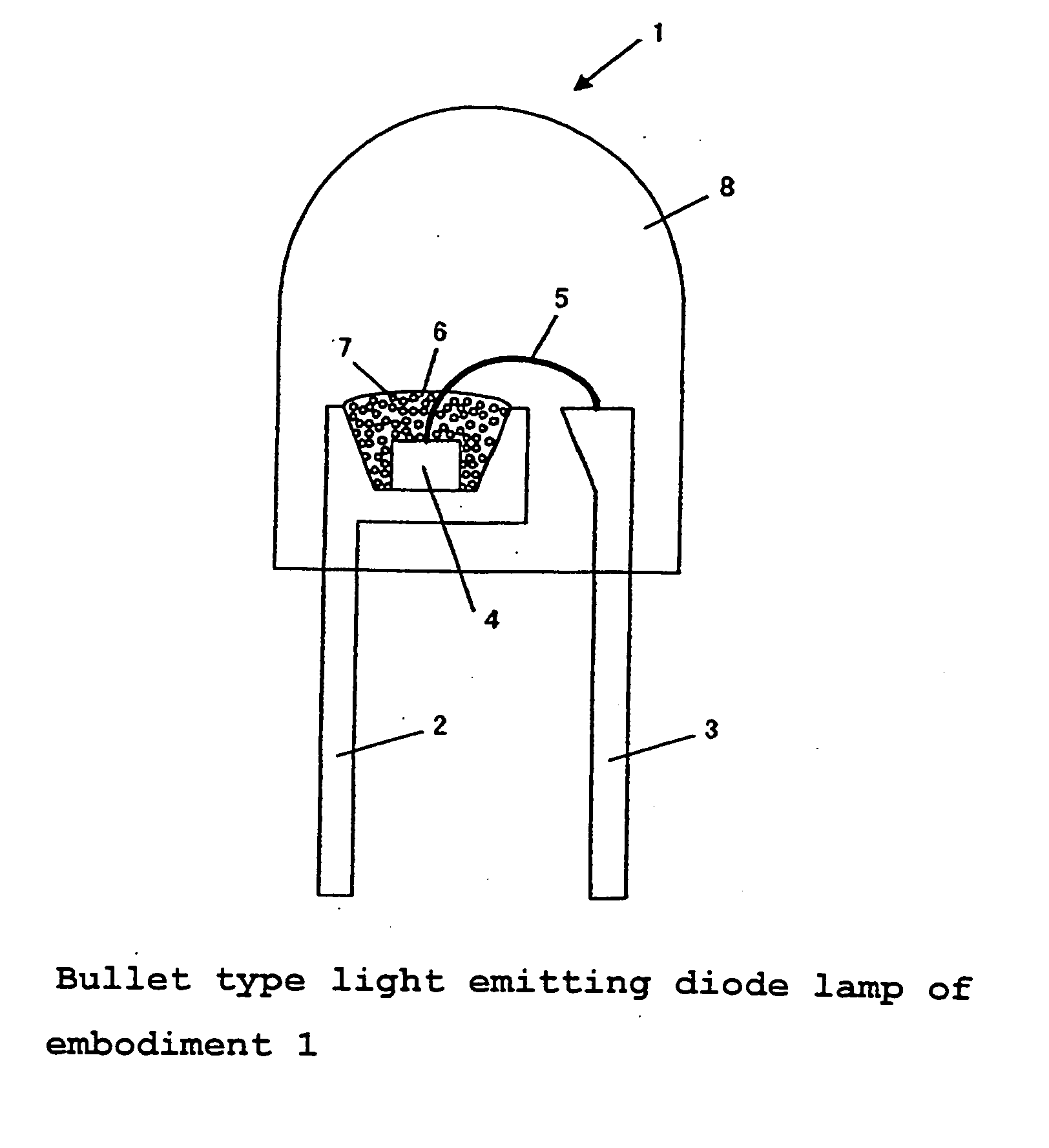
[0071] There was fabricated a so-called bullet-type white light emitting diode lamp (1) shown in FIG. 4.

[0072] It included two lead wires (2, 3), one (2) of which had a depression having a blue light emitting diode element (4) placed therein. The blue light emitting diode element (4) had a lower electrode electrically connected to a bottom surface of the depression by an electroconductive paste, and an upper electrode electrically connected to the other lead wire (3) via thin gold line (5). Mounted near the light emitting diode element (4) was a phosphor (7) which was obtained by mixing a first phosphor and a second phosphor and which was dispersed in a resin. The phosphors were dispersed in a first resin (6) which was transparent and which covered the whole of the blue light emitting diode element (4). Encapsulated in a second transparent resin (8) were the tip end of the lead wire including the depression, the blue light emitting diode element, and the first resin including the p...

embodiment 2

[0075] There was fabricated a chip-type white light emitting diode lamp (21) to be mounted on a substrate. Its configuration is shown in FIG. 6. It included a white alumina ceramic substrate (29) having a higher reflectivity to visible light, and, two lead wires (22, 23) fixed thereto, and the lead wires each included one end located at substantially the center position of the substrate, and the other end drawn out to the exterior to form an electrode to be soldered to an electric substrate upon mounting thereto. Placed onto and fixed to the one end of one (22) of the lead wires, was a blue light emitting diode element (24) so as to be located at the central portion of the substrate. The blue light emitting diode element (24) had a lower electrode electrically connected to the lead wire thereunder by an electroconductive paste, and an upper electrode electrically connected to the other lead wire (23) by a thin gold line (25).

[0076] Mounted near the light emitting diode element was ...

embodiment 3

[0077] There were adopted a number of bullet type light emitting diode lamps of the embodiment 1, to realize a highly decorative lighting apparatus (41) having an emission chromaticity varied in a gradation manner. FIG. 7 is a schematic view thereof. The lighting apparatus includes a laterally elongated upper support body (51), which is to be directly attached to a ceiling of a building or to be suspended therefrom by a chain or the like, thereby supporting the whole of the lighting apparatus (41). Accommodated in the support body (51) is an electric circuit of a light emitting diode lamp driving portion, which is supplied with an electric power from a mains-powered outside AC 100V electric-power source, thereby supplying an appropriate electric current to the light emitting diode lamps. The driving portion is connected to an electric-power source switch not shown and a dimmer dial not shown, thereby enabling the lighting electric-power source to be manually turned ON and OFF and th...


PUM

PropertyMeasurementUnit
emission wavelengthaaaaaaaaaa

Abstract

Conventional light emitting diode designs combined with blue light emitting diodes tend to lack in decorativeness and warmness. The present invention aims at providing a white light emitting diode for emitting white light with warmness at a higher luminance, and an intermediate color light emitting diode satisfying light emission in diversified color tones at a higher luminance.
The solving means resides in adoption of a fluorescent material which is configured to emit yellowish red or red light and which comprises a CaAlSiN3 crystal phase including, dissolved therein in a solid state, one kind or two or more kinds of element(s) selected from Mn, Ce, Pr, Nd, Sm, Eu, Gd, Tb, Dy, Ho, Er, Tm, Yb, and Lu, in a manner that the fluorescent material is mixed with another fluorescent material configured to emit green, yellowish green, or yellow light, and that the mixedly obtained phosphor is combined with a semiconductor light emitting element configured to emit bluish purple or blue light, to thereby fabricate a white light emitting diode for emitting white light with warmness at a high efficiency.

Description

TECHNICAL FIELD [0001] The present invention relates to a high-luminance white light emitting diode for lighting, an intermediate color light emitting diode for special decorative lighting, and lighting instruments adopting them. BACKGROUND ART [0002] There have been recently and extensively investigated white light emitting diodes each provided by combining a blue light emitting diode element and a blue-light absorbing / yellow-light emitting phosphor, and have been proposed and presented in various literatures including patent-related references (see patent-unrelated reference 1, and patent-related references 1 through 5, for example). Recently, lighting instruments, lighting equipments, and lighting apparatuses based on the aforementioned combination have been put into practical use. [0003] Known as one of phosphors so frequently used in the above applications, is a yttrium / aluminum / garnet based phosphor activated by cerium, represented by a general formula (Y, Gd)3(Al, Ga)5O12:Ce3...

Claims


Application Information

Patent Timeline
Patent Type & Authority Applications(United States)
IPC IPC(8): H01J1/62H01J63/04F21S8/04C09K11/08C09K11/64C09K11/77F21S2/00F21V5/04F21Y101/02H01L33/32H01L33/50H01L33/54H01L33/56H01L33/60H01L33/62
CPCC09K11/0883C09K11/7734C09K11/7774H01L33/502Y02B20/181H01L2224/45144H01L2224/48247H01L2224/48091H01L2924/00014H01L2924/00Y02B20/00C09K11/77348H01L33/54H01L33/50
Inventor HIROSAKI, NAOTOSAKUMA, KENUEDA, KYOTAYAMAMOTO, HAJIME
Owner NAT INST FOR MATERIALS SCI
Why Eureka
Try Eureka