Timing controller and timing control method

a timing controller and timing control technology, applied in the field of timing controller and timing control method, can solve the problems of significant reduction in amplification efficiency, disadvantage in particular to simple mobile communication devices and devices using a small-size battery, transmission signal (input signal) and voltage control signal v are slightly out of phase with each other, and achieve low distortion and high amplification efficiency

Inactive Publication Date: 2007-07-12
FUJITSU LTD
View PDF2 Cites 51 Cited by
  • Summary
  • Abstract
  • Description
  • Claims
  • Application Information

AI Technical Summary

Benefits of technology

[0010] According to one embodiment of the present invention, there are provided a device and a method for controlling the timing between the input signal and the voltage control signal of an amplifier in which the above-described disadvantage is eliminated.
[0011] According to one embodiment of the present invention, there are provided a device and a method for controlling the timing between the input signal and the voltage control signal of an amplifier in a linear transmitter that switches the supply voltage of the amplifier in accordance with the level of the input signal and outputs an output signal with little distortion with high amplification efficiency.
[0016] According to one aspect of the present invention, it is possible to suitably control the timing between the input signal and the voltage control signal of an amplifier with ease in a linear transmitter that switches the supply voltage of the amplifier in accordance with the level of the input signal and outputs an output signal with little distortion with high amplification efficiency.

Problems solved by technology

However, constant application of high supply voltage to the amplifier has the problem of significant reduction in amplification efficiency in the case of amplifying a small (low power) signal.
This is disadvantageous in particular to simple mobile communications devices and devices using a small-size battery.
As a result, there is concern that the transmission signal (input signal) and the voltage control signal v are slightly out of phase with each other.
However, since a voltage higher than the necessary supply voltage is applied to the amplifier, the efficiency of amplification is reduced.
Further, there is also concern that an unintended abrupt change forced on the output signal may result in the occurrence of an unnecessary frequency component.
Thus, if the input signal and the voltage control signal are not appropriately timed with each other, the degradation of a signal and the radiation of unnecessary waves are caused.
This problem of timing offset occurs product by product.
However, a method for automatically performing such compensation or control with efficiency has not been discovered, while performing it manually is time-consuming and unsuitable for controlling many products.

Method used


Image

  • Timing controller and timing control method
  • Timing controller and timing control method
  • Timing controller and timing control method

Examples


first embodiment

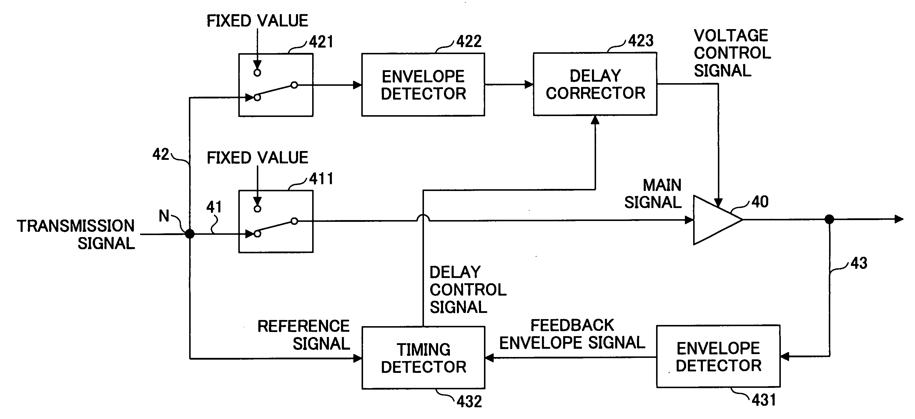
[0032]FIG. 4 is a block diagram showing part of a linear transmitter according to a first embodiment of the present invention.

[0033] Referring to FIG. 4, the linear transmitter includes an amplifier 40, a main signal channel 41 provided on the input side of the amplifier 40, a control signal channel 42 provided on the control signal side of the amplifier 40, and a feedback channel 43 provided on the output side of the amplifier 40. In the main signal channel 41, a switch 411 is provided between a node N to which a signal to be transmitted (a transmission signal) is fed and the input port of the amplifier 40. In the control signal channel 42, a switch 421 connected to the node N and an envelope detector part 422 connected to the output of the switch 421 are provided, and a delay corrector part 423 is provided between the output of the envelope detector part 422 and the control port of the amplifier 40. In the feedback channel 43, an envelope detector part 431 connected to the output...

second embodiment

[0050] A description is given below of a second embodiment according to the present invention.

[0051] Any signal may be employed as a transmission signal used in measuring the channel delay. However, in terms of improving measurement accuracy, it is preferable to use a test signal having a special waveform. FIG. 11 shows the case where an impulse signal is used as a test signal. As graphically represented, the delay is determined by measuring the interval between pulses. Accordingly, the period in the case of sequentially transmitting pulses should be sufficiently longer than the delay. FIG. 12 shows the case where a two-tone signal is used as a test signal. In this case, the delay is determined by comparing the amplitudes of the two-tone signal. In terms of improving measurement accuracy, preferably, the two-tone signal has a low frequency. If the frequency is high, the waveform period becomes short so that it may be impossible to determine a large delay difference. Employment of t...

third embodiment

[0052]FIG. 13 is a block diagram showing a transmission part of a linear transmitter using a timing controller according to a third embodiment of the present invention. According to this embodiment, a delay measurement part 44 including the envelope detector part 431 and the timing detector part 432 is removably attached to the main body of the linear transmitter through connectors 441, 442, and 443. This embodiment is preferable in terms of simplifying the configuration of the linear transmitter.

[0053] According to one embodiment of the present invention, the delay difference between a main signal channel and a control channel is measured by suitably switching each of a main signal switch to select one of an input signal and a signal representing a fixed value and a control signal switch to select one of the input signal and the signal representing the fixed value. A channel delay is controlled so as to cancel this delay difference. More specifically, the delay difference is deter...


PUM


Abstract

A timing controller is disclosed that includes: an amplifier part configured to amplify a first input signal in accordance with a control voltage, the first input signal being one of a transmission signal and a signal of a fixed value; a detector part configured to detect envelope information from the output signal of the amplifier part; a controller part configured to determine a delay difference from the transmission signal and the envelope information and transmit a timing control signal based on the delay difference; and a delay corrector part configured to correct the delay of a second input signal in accordance with the timing control signal, the second input signal being one of the transmission signal and a signal of a fixed value. One of the first and second input signals employs the corresponding signal of the fixed value in the case of correcting the delay.

Description

BACKGROUND OF THE INVENTION [0001] 1. Field of the Invention [0002] The present invention relates generally to the technical field of an amplifier employed in high frequency bands, and more particularly to a device and method for controlling the timing between the input signal and the voltage control signal of the amplifier. [0003] 2. Description of the Related Art [0004] In a linear transmitter, a signal to be transmitted (transmission signal) is linearly amplified and transmitted. In order to linearly amplify signals of various (power) levels ranging from low to high, it is necessary to supply power to the amplifier based on a high level signal. However, constant application of high supply voltage to the amplifier has the problem of significant reduction in amplification efficiency in the case of amplifying a small (low power) signal. This is disadvantageous in particular to simple mobile communications devices and devices using a small-size battery. In order to cope with such a p...

Claims


Application Information

Patent Timeline
Patent Type & Authority Applications(United States)
IPC IPC(8): H03G3/10
CPCH03F1/0222H03F1/32
Inventor ISHIKAWA, HIROYOSHINAGATANI, KAZUOHAMADA, HAJIMEFUDABA, NOBUKAZUKUBO, TOKURO
Owner FUJITSU LTD
Why Eureka
Try Eureka