Forming an antenna beam using an array of antennas to provide a wireless communication

a technology of wireless communication and array of antennas, applied in the field of wireless communication, can solve the problems of unfavorable wireless communication, multi-path and co-channel interference, and different types of mechanical and/or electrical deformation of antennas,

Active Publication Date: 2007-07-12
ALCATEL-LUCENT USA INC +1
View PDF1 Cites 30 Cited by
  • Summary
  • Abstract
  • Description
  • Claims
  • Application Information

AI Technical Summary

Problems solved by technology

However, antennas, among other things, may suffer from different types of mechanical and / or electrical deformations.
Some antenna deformations also affect the radiation pattern from a source causing multi-paths and co-channel interference.
A cellular antenna may include an array of antenna elements in that a deformed antenna array may alter a phase of an antenna signal and thus antenna lobes (e.g., main, rear and side), resulting in an undesired beam pattern.
However, as the network capacity and number of cells increase, network throughput and capacity suffers due to cellular antenna deformations.
Moreover, as the number of cells increase, antenna deformations may become prime sources of cell-to-cell interference.
That is, an antenna deformation may result in a significant degradation in a vital network performance metric in digital cellular systems.
However, this constraint results in a significantly less reinforced or weaker structure for an array antenna of radiating or radar elements.
When using such a weaker reinforcement structure, the shape or flatness of the antenna array may be difficult to control.
Moreover, as the number of antenna elements increase to provide a narrow antenna beam, the number of errors of phase, which may affect the main lobe of the antenna beam, also increase.
In other words, an array environment comprising a large number of antenna elements may fail to focus the main lobe of the antenna beam because the location of each antenna element relative to a deformed aperture of the antenna array.
However, any undesired shift in the antenna beam may provide a radiation pattern that requires constant adjustment.

Method used


Image

  • Forming an antenna beam using an array of antennas to provide a wireless communication
  • Forming an antenna beam using an array of antennas to provide a wireless communication
  • Forming an antenna beam using an array of antennas to provide a wireless communication

Examples


Embodiment Construction

[0030] Illustrative embodiments of the invention are described below. In the interest of clarity, not all features of an actual implementation are described in this specification. It will of course be appreciated that in the development of any such actual embodiment, numerous implementation-specific decisions may be made to achieve the developers' specific goals, such as compliance with system-related and business-related constraints, which will vary from one implementation to another. Moreover, it should be appreciated that such a development effort might be complex and time-consuming, but may nevertheless be a routine undertaking for those of ordinary skill in the art having the benefit of this disclosure.

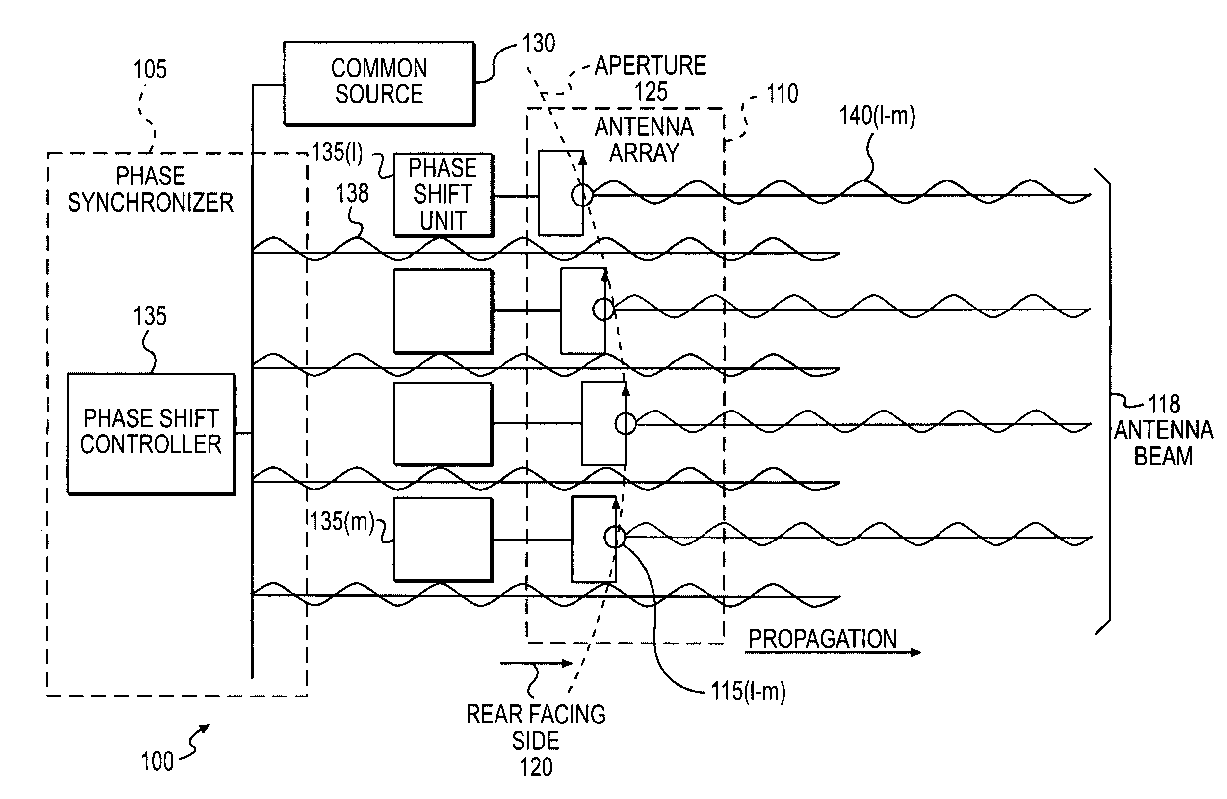
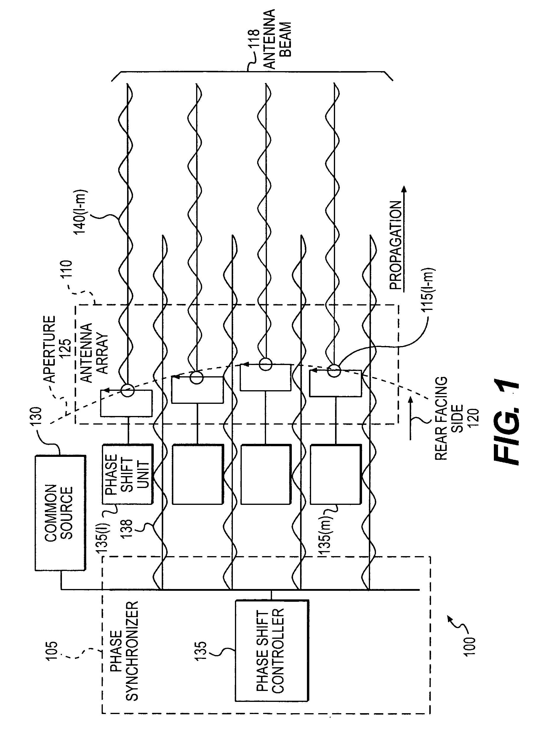
[0031] Generally, a method and an apparatus are provided for forming an antenna beam from an array antenna having a rear facing side, an aperture, and including a first and a second radiating element. The method comprises injecting a synchronization signal wirelessly from a comm...


PUM


Abstract

The present invention provides a method and an apparatus for forming an antenna beam from an array antenna having a rear facing side, an aperture, and including a first and a second radiating element. The method comprises injecting a synchronization signal wirelessly from a common source at the rear facing side of the array antenna to provide an initial calibration of the array antenna that synchronizes phase of an output signal from the first and second radiating elements to the common source. The method further comprises compensating a change in phase of the synchronization signal at the first radiating element based on a spatial displacement to synchronize phase of a first portion of the output signal from the first radiating element to the phase of the synchronization signal at the second radiating element in response to the spatial displacement of the first radiating element after the initial calibration of the antenna array. A synchronization source may couple to the phased array antenna wirelessly, such as optically or using radio frequency based coupling. To synchronize a portion of an output signal from a plurality of radiating elements, a phase shift unit and / or a time delay unit at each radiating element may lock its phase to a synchronization signal from a common or a point source regardless of a location thereof relative to the synchronization source. In this way, a synchronization source may synchronize the phase of the phased array antenna even if one or more radiating elements may move from an original spatial location to any arbitrary position.

Description

BACKGROUND OF THE INVENTION [0001] 1. Field of the Invention [0002] This invention relates generally to telecommunications, and more particularly, to wireless communications. [0003] 2. Description of the Related Art [0004] In a telecommunication system, network planning and an optimal installation and deployment of network infrastructure components is important in order to increase system capacity and maximize network coverage. For example, a plurality of communication nodes, such as base stations with antennas may be geographically distributed across a coverage area. While locations of these communication nodes may be difficult to change, antennas provide mechanisms with which the antenna may be adapted to the various needs of a wireless network. Therefore, antennas play a crucial role in telecommunication systems, such as in digital cellular networks. [0005] However, antennas, among other things, may suffer from different types of mechanical and / or electrical deformations. For exa...

Claims


Application Information

Patent Timeline
Patent Type & Authority Applications(United States)
IPC IPC(8): H01Q3/00G01S5/02H01Q21/00G01S19/46G01S19/44
CPCH01Q3/267H01Q3/30H01Q3/2676
Inventor BOLLE, CRISTIAN A.METZ, CARSTEN
Owner ALCATEL-LUCENT USA INC
Why Eureka
Try Eureka