System for EMI/RFI filtering and transient voltage suppression

Inactive Publication Date: 2007-07-12
RANDALL MICHAEL STEVEN +1
View PDF6 Cites 29 Cited by
  • Summary
  • Abstract
  • Description
  • Claims
  • Application Information

AI Technical Summary

Benefits of technology

[0012] A particular advantage of the present invention is the ability of the device to act as a faraday cage in the company of a suitable design, enabling an additional dimension of electromagnetic noise isolation.
[0013] Another particular advantage of the present invention is the ability to have improved device density capability and excellent volumetric efficiency over conventional EMI/RFI and transient voltage suppression devices.
[0014] These and other advantages are provided in a device comprising of two diverse types of flexible and electrically conductive wires that are woven or interlaced in a non-lateral configuration. The primary wire is a flexible and/or bendable, conductive core, double clad, edifice which promotes one direction of electron flow across the device. The succeeding wire is of a conventional, flexible, single or multiple strands, non insulated type which promotes a divergent direction of electron flow across the device.
[0015] The primary wire is a nano-composite consisting of a core-clad-clad structure. The core of the wire is comprised of a flexible conductor material that acts as the transmission structure. The inner clad of the primary wire is comprised of a dielectric or ferrite material formed or deposited suitably on the surface of the largely conductive core in the case of EMI filtering, or is comprised of a varistor material formed on the core in the case of transient voltage suppression. The outer clad of the primary wire is comprised of an electrically conductive la

Problems solved by technology

EMI is any electrical disturbance that interferes with normal operation of electronic equipment.
Increased electronic system densities and speed have led to a concern of electric

Method used


Image

  • System for EMI/RFI filtering and transient voltage suppression
  • System for EMI/RFI filtering and transient voltage suppression
  • System for EMI/RFI filtering and transient voltage suppression

Examples


Example

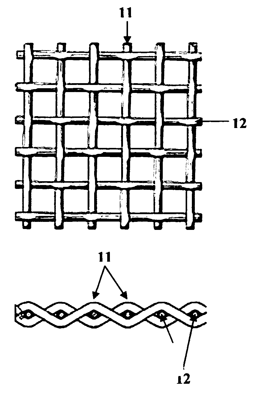
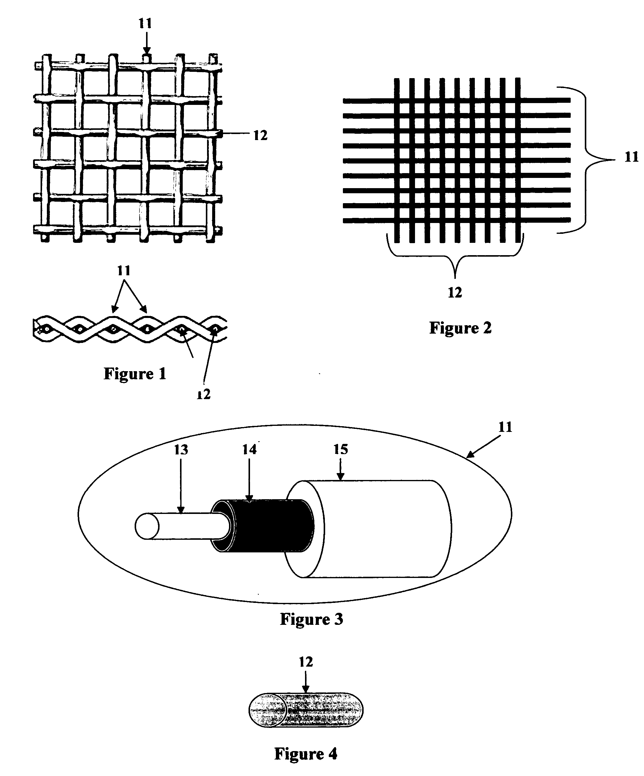
[0026]FIGS. 1 and 2 are perspective views of a flexible, woven or interlaced, electronic system for electronic EMI / RFI (Electromagnetic Interference / Radio Frequency Interference) filtering and for Transient Voltage Suppression. This filtering system consists of two diverse types of flexible and electrically conductive wires that are woven or interlaced into a fabric through the use of textile technologies and / or practices. The primary wire 11 is a flexible or bendable, conductive core, double clad, edifice which promotes one direction of electron flow across the woven material (the “warp” of the fabric). The succeeding wire 12 is of a conventional, flexible, single or multiple strands, non-insulated type which promotes a divergent direction of electron flow across the woven material (the “weft” of the fabric). Variation in weave or interlacement pattern, design, and wire count per unit length (I / O or input / output or strand density) are determined by design and are dependent upon pro...


PUM


Abstract

A woven or interlaced electronic system for electronic EMI/RFI (Electromagnetic Interference/Radio Frequency Interference) filtering and for Transient Voltage Suppression. This filtering system consists of two diverse types of flexible and electrically conductive wires that are woven or interlaced into a fabric through the use of textile technologies and/or practices. The primary wire is a flexible or bendable, conductive core, single or double clad, edifice which promotes one direction of electron flow across the woven material (the “warp” of the fabric). The succeeding wire 12 is of a conventional, flexible, single or multiple strands, non-insulated type which promotes a divergent direction of electron flow across the woven material (the “weft” of the fabric).

Description

BACKGROUND OF THE INVENTION [0001] The present invention is related to a Provisional Patent Ser. No. 60 / 642,491 filed Jan. 10, 2005, which relates to an electronic device comprised of a woven or interlaced structure of composite and / or non-composite conductive wire assemblies that may be used without a substrate, or with a flexible substrate or mounted onto, or imbedded within, a rigid circuit board or an electronic substrate and a method of manufacture thereof, and particularly relates to an electronic device of a woven or interlaced structure that is to be used mainly for the filtering of Electromagnetic interference (EMI), Radio Frequency Interference (RFI) and / or transient voltage suppression, and a method of manufacturing such a device. [0002] With the progress of scientific technologies, the making of electronic equipment more compact and higher in performance is being demanded. As systems shrink in size, become more compact and portable, and more networked / interconnected, EMC...

Claims


Application Information

Patent Timeline
IPC IPC(8): H02H3/22
CPCH05K9/009
Inventor RANDALL, MICHAEL STEVENANTONIADES, COREY
Owner RANDALL MICHAEL STEVEN
Why Eureka
Try Eureka