Gas discharge laser light source beam delivery unit

a laser light source and laser light source technology, applied in the field of gas discharge laser light source beam delivery units, can solve the problems of affecting the life of optics, affecting the optics, and extremely difficult to achieve, and the optics are extremely important and difficult to live long

Inactive Publication Date: 2007-07-12
CYMER INC
View PDF51 Cites 4 Cited by
  • Summary
  • Abstract
  • Description
  • Claims
  • Application Information

AI Technical Summary

Problems solved by technology

Long optics life is extremely important and extremely difficult to achieve in vacuum ultraviolet light (“VUV”) and other deep ultraviolet (“DUV”) and extreme ultraviolet (“EUV”) applications.
These excimer lasers, when used for integrated circuit lithography, are typically operated in an integrated circuit fabrication line “around-the-clock” producing many thousands of valuable integrated circuits per hour; therefore, down-time can be very expensive.
Exposure to open air is detrimental to optics life, i.e., when the purge environment is breached.
There are occasions where the previous methods of aligning the BDU and / or the BDU modules using a prior, e.g., total station technique may not be feasible, e.g., due to space limitations, i.e., close proximity to other elements f the laser system or surrounding structures or machinery and / or small working areas, e.g., prohibiting open beam alignment.
The BDU system, e.g., when operating at 193 um wavelength can have a hard time achieving optics element / module long lifetimes, e.g., due to the effects of contamination on the optics.
One of the biggest problems confronted by the BDU system design can be, e.g., in-situ beam alignment.
In-situ, open beam alignment, e.g., can be very detrimental to optics life.
Some lasers, e.g., XLA lasers may have uneven spatial coherence, which is a problem that needs to be corrected.

Method used


Image

  • Gas discharge laser light source beam delivery unit
  • Gas discharge laser light source beam delivery unit
  • Gas discharge laser light source beam delivery unit

Examples


Embodiment Construction

[0025] An aspect of an embodiment of the present invention establishes, e.g., proven materials, design configurations, and cleaning processes that when implemented result in achieving required optic lifetimes, e.g., on the order of >12 billion pulses. Optic lifetimes are measured, e.g., in terms of some % of transmission loss. Transmission loss of less than 1% over 12 billion pulses is accomplished according to aspects of an embodiment of the present invention.

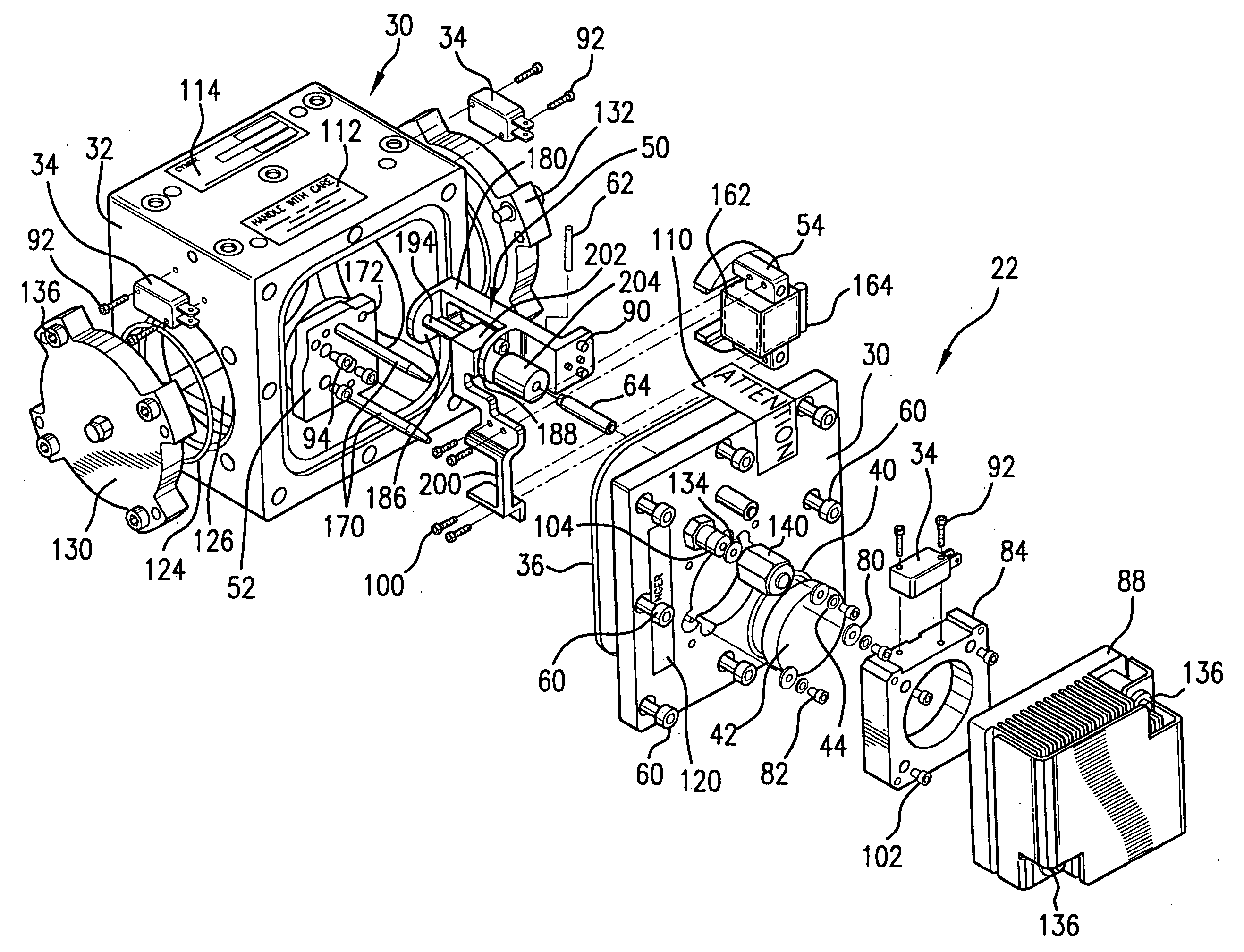
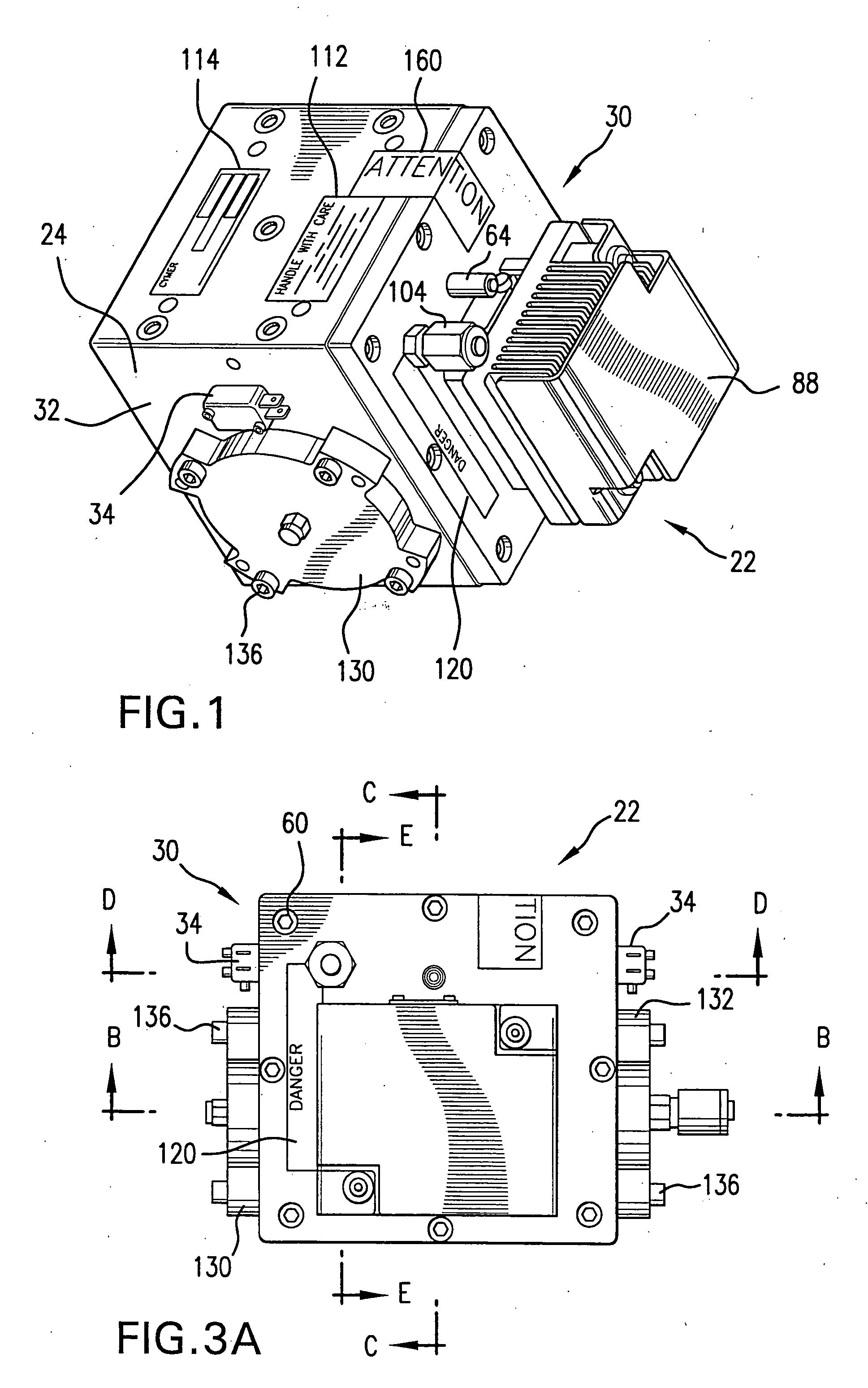
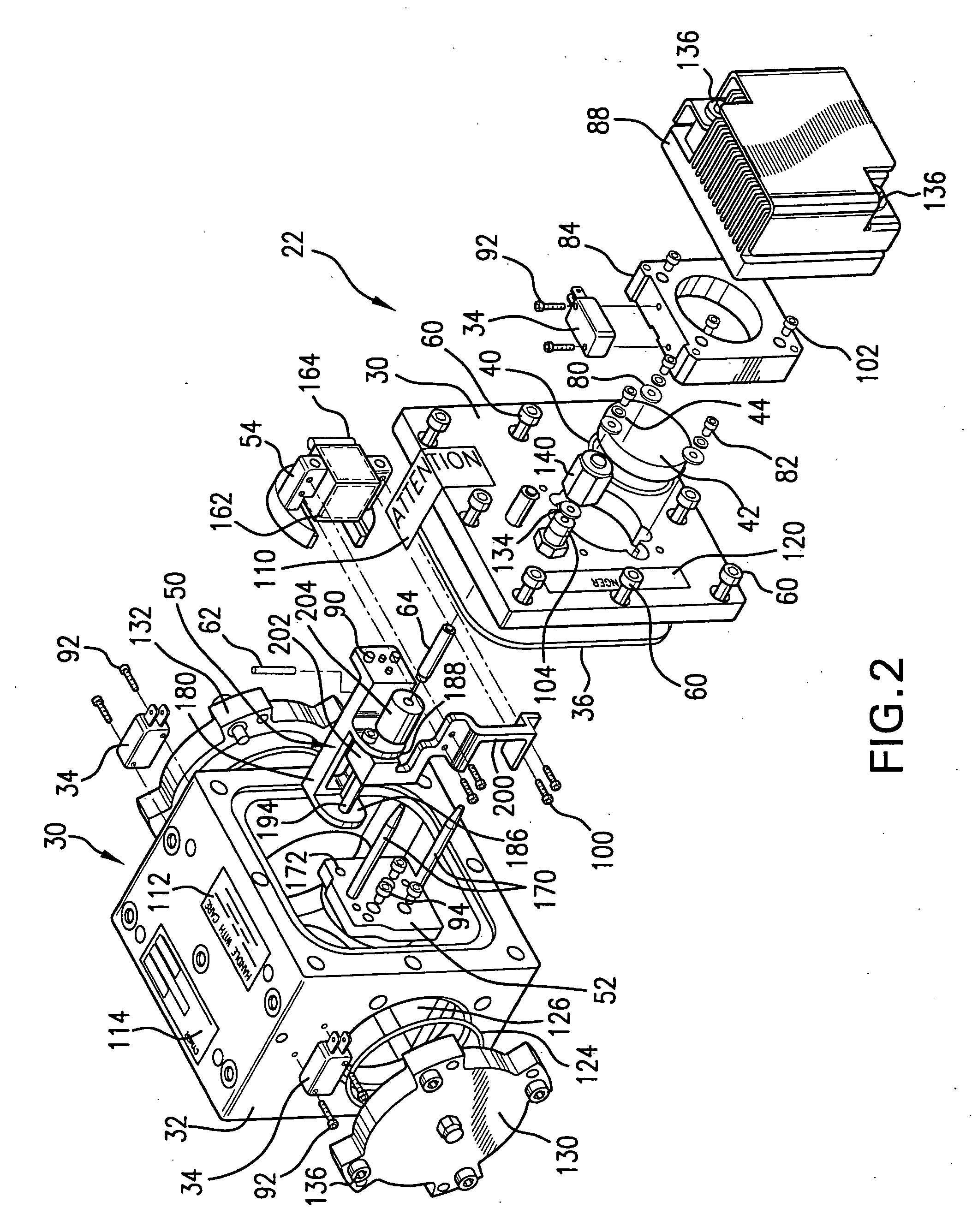
[0026] According to another aspect of an embodiment of the present invention there is provided, e.g., a method and apparatus for in-situ optics module replacement without open air contamination of the rest of the BDU system. The module can, e.g., be used wherever necessary to control contamination to the BDU due to potential module repair / maintenance / replacement.

[0027] According to aspects of another embodiment of the present invention beam alignment, power measurements, and beam analysis can be provided without exposure to ...


PUM

PropertyMeasurementUnit
charging voltageaaaaaaaaaa
voltage electrical potentialaaaaaaaaaa
diameteraaaaaaaaaa

Abstract

A beam delivery unit and method of delivering a laser beam from a laser light source for excimer or molecular fluorine gas discharge laser systems in the DUV and smaller wavelengths is disclosed, which may comprise: a beam delivery enclosure defining an output laser light pulse beam delivery path from an output of a gas discharge laser to an input of a working apparatus employing the light contained in the output laser light pulse beam; a purge mechanism operatively connected to the beam delivery enclosure; an in-situ beam parameter monitor and adjustment mechanism within the enclosure, comprising a retractable beam redirecting optic; a beam analysis mechanism external to the enclosure; and, a retraction mechanism within the enclosure and operable from outside the enclosure and operative to move the retractable beam redirecting optic from a retracted position out of the beam path to an operative position in the beam path. The BDU may also include a beam attenuator unit contained within the enclosure adjustably mounted within the enclosure for positioning within the beam delivery path. The BDU may have at least two enclosure isolation mechanisms comprising a first enclosure isolation mechanism on a first side of the enclosure from the at least one optic module and a second enclosure isolation mechanism on a second side of the enclosure from the at least one optic module, each respective enclosure isolation mechanism comprising a flapper valve having a metal to metal seating mechanism and a locking pin assembly. A precision offset ratchet driver operative to manipulate actuator mechanisms in difficult to reach locations may be provided. An external kinematic alignment tool may be provided. A method of contamination control for a BDU is disclosed comprising selection of allowable materials and fabrication processes.

Description

RELATED APPLICATIONS [0001] The present application is a continuation of U.S. application Ser. No. 10 / 739,961, filed on Dec. 17, 2003, which is a continuation-in-part of United States Published Patent Application No. US / 20020191654A1, entitled LASER LITHOGRAPHY LIGHT SOURCE WITH BEAM DELIVERY, with inventors Klene, et al., published on Dec. 19, 2002, based upon a U.S. application Ser. No. 10 / 141,216, filed on May 7, 2002; and United States Published Patent Application No. US / 20030043876A1, entitled LITHOGRAPHY LASER WITH BEAM DELIVERY AND BEAM POINTING CONTROL, with inventors Lublin et al., published on Mar. 6, 2003, based upon a U.S. Application Ser. No. 10 / 233,253 filed on Aug. 30, 2002; and United States Patent Published Application No. US / 20030091087A1, entitled LITHOGRAPHY LASER SYSTEM WITH IN-PLACE ALIGNMENT TOOL, with inventors Ershov et al., published on May 15, 2003, based upon a U.S. application Ser. No. 10 / 255,806, filed on Sep. 25, 2002; and U.S. application Ser. No. 10 / ...

Claims


Application Information

Patent Timeline
Patent Type & Authority Applications(United States)
IPC IPC(8): H01S3/22G03F7/20H01SH01S3/00H01S3/03H01S3/036H01S3/038H01S3/04H01S3/041H01S3/08H01S3/0943H01S3/097H01S3/0971H01S3/0975H01S3/102H01S3/104H01S3/105H01S3/11H01S3/13H01S3/134H01S3/139H01S3/223H01S3/225H01S3/23
CPCB23K26/12B23K26/128G01J1/04G01J1/0418G01J1/4257G01J2001/0285G03F7/70025G03F7/70041G03F7/7055G03F7/70575G03F7/70933H01S3/005H01S3/0057H01S3/0071H01S3/02H01S3/03H01S3/036H01S3/038H01S3/0385H01S3/0404H01S3/041H01S3/08004H01S3/08009H01S3/0943H01S3/097H01S3/09705H01S3/0971H01S3/0975H01S3/104H01S3/105H01S3/1305H01S3/134H01S3/139H01S3/22H01S3/2207H01S3/223H01S3/225H01S3/2251H01S3/2256H01S3/2258H01S3/2333H01S3/2366B23K26/426B23K26/705
Inventor DAS, PALASH P.AHMED, KHURSHIDFRANCIS, GREGORYGLATZEL, HOLGERLUKASHEV, ALEXEITYLER, JEREMYWEBB, R. KYLE
Owner CYMER INC
Why Eureka
Try Eureka