
Analysing biological entities

a biological entity and analysis method technology, applied in the field of biological entity analysis, can solve the problems of nucleic acid deterioration rate limitation, damage to the nucleic acid structure, and toxic nucleic acid, etc., and achieve the effect of accurate and reliabl

Inactive Publication Date: 2007-07-12
GE HEALTHCARE LTD
View PDF10 Cites 34 Cited by
  • Summary
  • Abstract
  • Description
  • Claims
  • Application Information

AI Technical Summary

Benefits of technology

"The invention provides a method for analyzing multiple biological entities using an imaging apparatus. The method involves using a marker to identify objects within the biological entities and recording an image of the entities during two different time periods. The marker is less capable of identifying objects during the second time period. The method also involves generating a spatial definition for an object in the first image using data derived from the marked-up image. This allows for more accurate and reliable analysis of the biological entities and screening of chemical compounds over an extended time period. The invention also provides a method for image analysis that can be conducted at a different time and location."

Problems solved by technology

However, the nuclear dye is destructive to the structure of the nucleic acid and hence multiple samples of cells are required to study the progression of biological activity over time.
In the case where many hundreds of samples are to be analysed, this deterioration of the nucleic acid can become rate limiting.
This intercalation, however, over the course of an experiment having an extended time period proves to be toxic to the nucleic acid.
The toxicity results in damage to the structure of the nucleic acid leading to mutations in the genetic code.
These mutations interfere with the correct functioning of the cell and in the case of screening chemical compounds for their effects on biological cell systems, introduces undesired errors into results data being collected.

Method used


Image

  • Analysing biological entities
  • Analysing biological entities
  • Analysing biological entities

Examples


first embodiment

[0085] The imaging system preferably resides within a light-proof enclosure. In a first embodiment, the sample plate is maintained at the desired temperature by maintaining the entire interior of the enclosure at that temperature. At 37° C., however, unless elevated humidity is purposefully maintained, evaporation cooling will reduce the sample volume limiting the assay duration.

second embodiment

[0086] A second embodiment provides a heated cover for the microwell plate which allows the plate to move under the stationary cover. The cover has a single opening above the well aligned with the optical axis of the microscope. This opening permits dispensing into the active well while maintaining heating and limited circulation to the remainder of the plate. A space between the heated cover plate and microwell plate of approximately 0.5 mm allows free movement of the microwell plate and minimizes evaporation. As the contents of the interrogated well are exposed to ambient conditions though the dispenser opening for at most a few seconds, said contents suffer no significant temperature change during the measurement.

third embodiment

[0087] In a third embodiment, a thin, heated sapphire window is used as a plate bottom enclosure. A pattern of resistive heaters along the well separators maintain the window temperature at the desired level.

[0088] In additional embodiments, the three disclosed methods can be variously combined.

[0089] In an additional preferred embodiment of the invention, employed in automated screening assays, the imaging system is integrated with plate-handling robots, such as the Zymark Twister.

Data Processing System

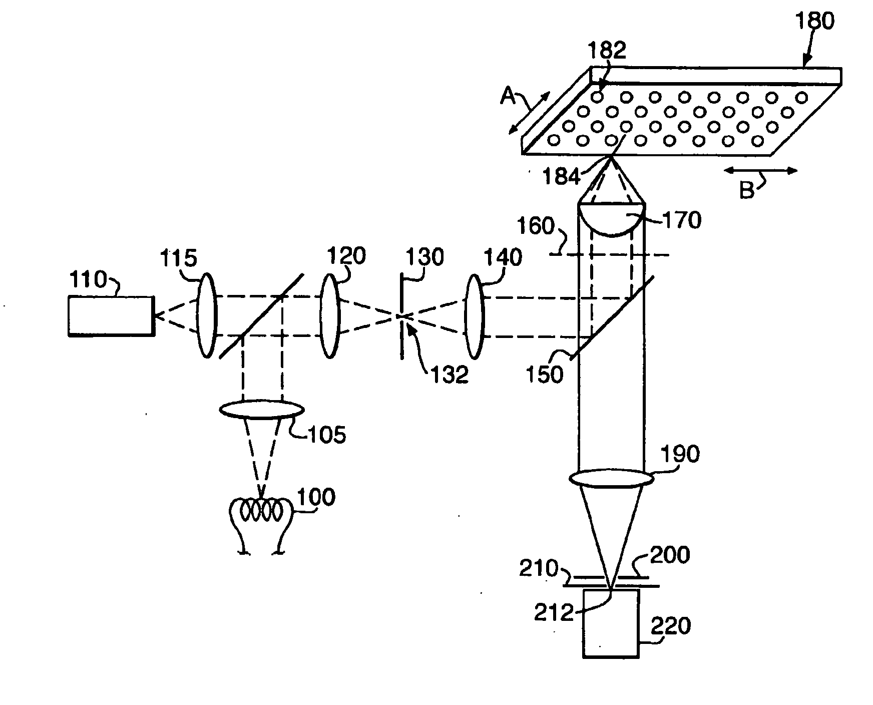
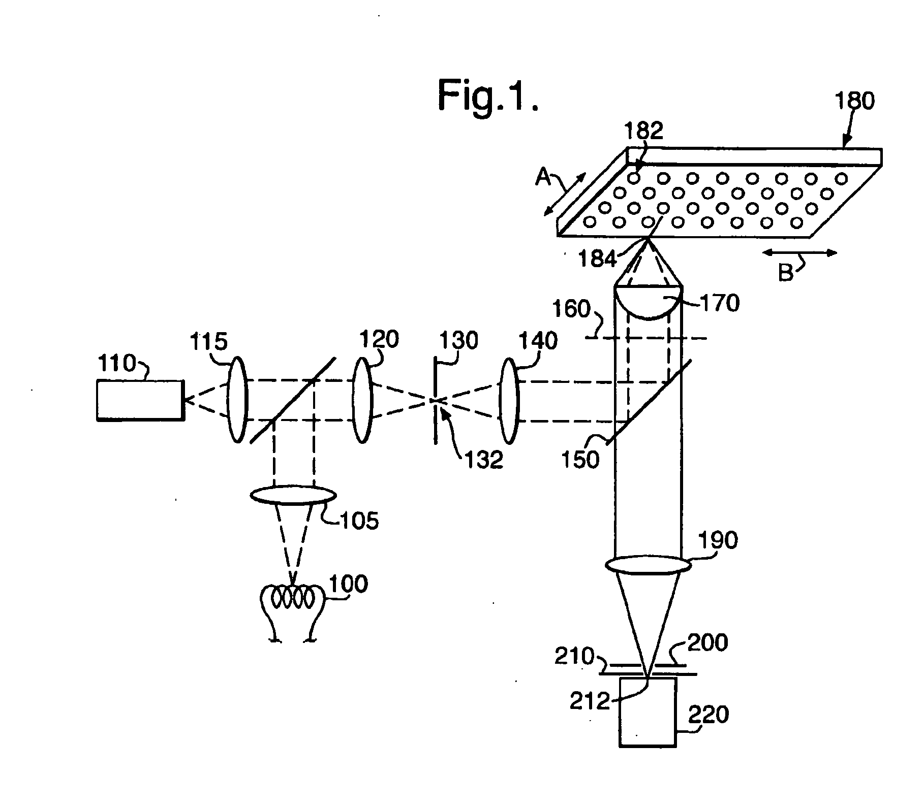
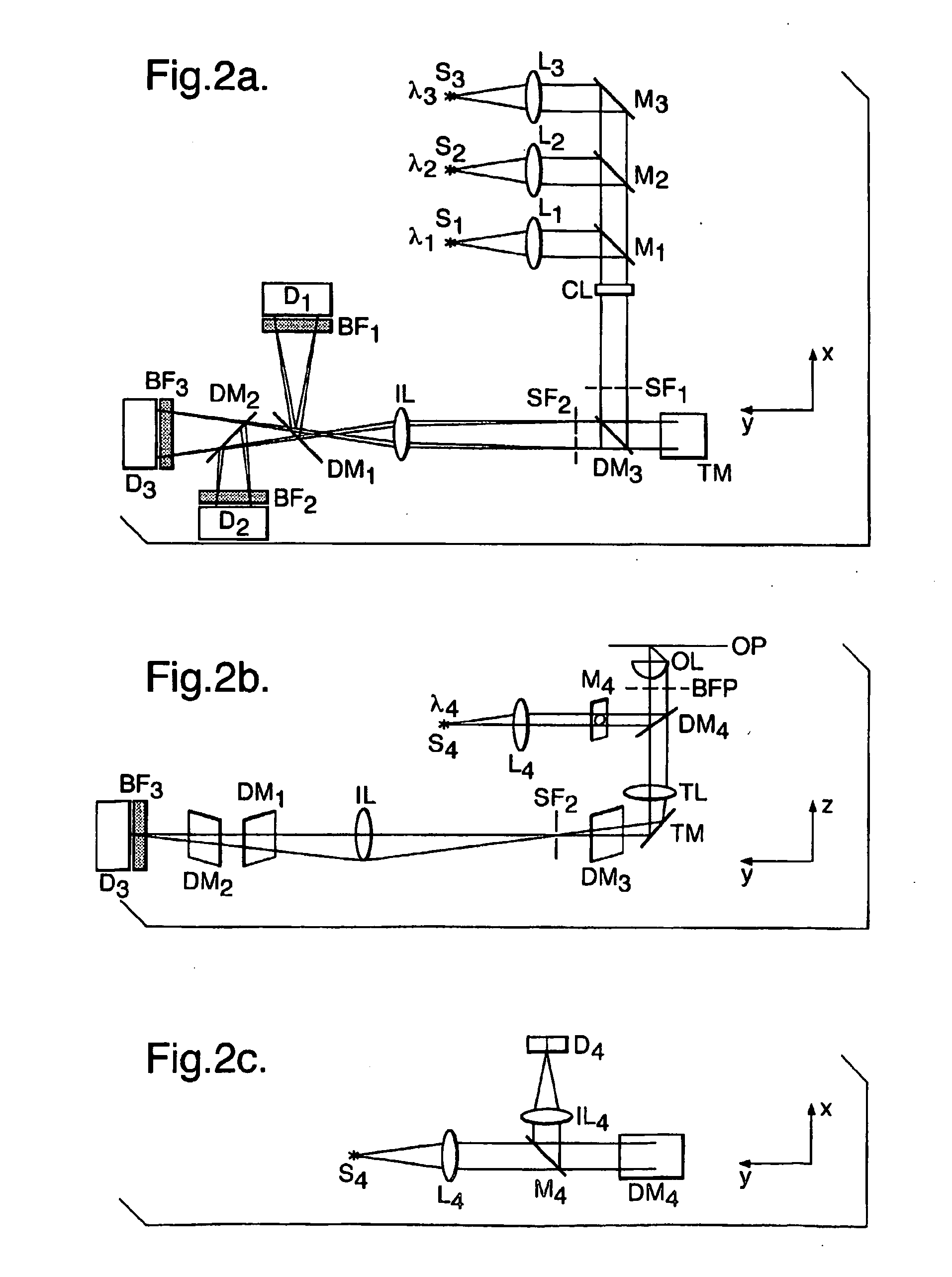
[0090]FIG. 6 shows a schematic illustration of data processing components of a system arranged in accordance with the invention. The system, based on the Amersham Biosciences IN Cell Analyzer™ system, includes a confocal microscope 400 as described above, which includes the detectors D1, D2, D3, D4, D5, the switch SW, a control unit 401, an image data store 402 and an Input / Output (I / O) device 404. An associated computer terminal 405 includes a central processing unit (CPU) 408, ...


PUM

PropertyMeasurementUnit
lengthaaaaaaaaaa
lengthaaaaaaaaaa
depth resolutionaaaaaaaaaa

Abstract

A method of analysing a plurality of biological entities using an imaging apparatus. The method comprises: providing a marker for said plurality of biological entities, said marker being capable of identifying objects within said plurality of biological entities when detected using the imaging apparatus, the method of provision being arranged such that said marker is capable of identifying said objects during a first time period, and said marker is less capable of identifying said objects during a second time period; during the first time period, recording a marked-up image in which spatial definitions of said objects are identifiable from said marker; during the second time period, recording a first image of said plurality of biological entities; and generating a spatial definition for an object in said first image using data derived from said marked-up image.

Description

CROSS REFERENCE TO RELATED APPLICATIONS [0001] This application is a filing under 35 U.S.C. § 371 and claims priority to international patent application number PCT / GB2004 / 003247 filed Jul. 28, 2004, published on Feb. 10, 2005 as WO2005 / 012880 and also claims priority to patent application number 0317679.9 filed in the Great Britain Patent Office on Jul. 29, 2003; the disclosures of which are incorporated herein by reference in their entireties.FIELD OF THE INVENTION [0002] The present invention relates to a method of analysing biological entities, in particular but not exclusively biological cells. The invention further relates to computer software and apparatus adapted to carry out such a method. BACKGROUND OF THE INVENTION [0003] Currently in drug discovery and development and in general biological research, methods and apparatus for accurately performing cell-based assays are used. Cell-based assays are advantageously employed for assessing the biological activity of chemical co...

Claims


Application Information

Patent Timeline
Patent Type & Authority Applications(United States)
IPC IPC(8): G06K9/00G01N1/30
CPCG01N2021/6439G01N1/30
Inventor ARINI, NICHOLAS S.GOODYER, IAN D.RUEHLMANN, DIETRICH O.THOMAS, NICHOLAS
Owner GE HEALTHCARE LTD
Learn More