Apparatus on a spinning preparation machine for monitoring and/or adjusting clearances at components

a technology of preparation machine and apparatus, which is applied in the direction of drafting machine, safety device for fibre treatment, textiles and paper, etc., can solve the problems of affecting the operation of the equipment, affecting the clearance between the roller and the cleaning or carding elements, and affecting the effect of the equipmen

Active Publication Date: 2007-07-19
TRÜTZSCHLER GRP SE
View PDF4 Cites 3 Cited by
  • Summary
  • Abstract
  • Description
  • Claims
  • Application Information

AI Technical Summary

Benefits of technology

[0024] In a further advantageous embodiment of the invention, the electrical capacitance between the components facing one another is determinable and, on departure from a desired capacitance, a signal is generated for an adjustment process or a switching-off process. By means of measuring the capacitance and comparing it with a desired value, the...

Problems solved by technology

Owing to the heat generated in operation and owing to the roller expansion caused by centrifugal force during rotation, the clearance between the roller and the cleaning or carding elements diminishes.
In the process, if the adjustment was not effected according to specifications, it may happen that these elements touch the roller during operation.
This contact often leads to further heating and to an associated contact pressure on the clothing, with the result that this may “burst”.
This is associated with considerable consequential damage.
In consequence of misadjustments or incorrect machine operation, carding machines may crash.
The repair costs for such crashes are substantial.
Contact between a stationary component and, for example, a carding cylinder, has destructive consequences, because due to the setting of its abrasive teeth the roller clothing exerts a strong pulling action on components on contact therewith, and when contact is discovered, for example, by an operator, the rollers take at least five minutes to run down to a standstill.
Damage escalates during this time.
Increasing volumetric flow rate of fibre material (output), even with a working area that remains constant, leads to increased generation of heat d...

Method used


Image

  • Apparatus on a spinning preparation machine for monitoring and/or adjusting clearances at components
  • Apparatus on a spinning preparation machine for monitoring and/or adjusting clearances at components
  • Apparatus on a spinning preparation machine for monitoring and/or adjusting clearances at components

Examples


Embodiment Construction

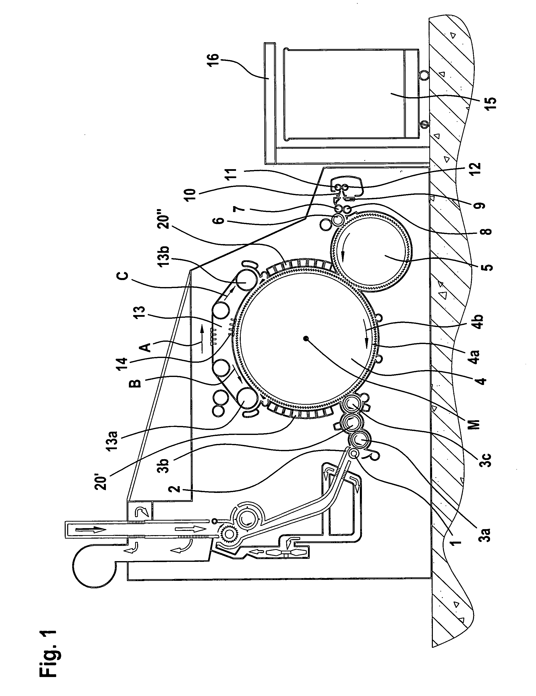
[0035] Referring to FIG. 1, a flat card for example, a flat card TC 03 (Trade Mark) made by Trützschler GmbH & Co. KG. of Mönchengladbach, Germany, has feed roller 1, feed table 2, licker-ins3a, 3b, 3c, cylinder 4, doffer 5, stripping roller 6, squeezing rollers 7, 8, web deflector 9, web funnel 10, take-off rollers 11, 12, revolving flat 13 with flat guide rollers 13a, 13b and flat bars 14, can 15 and can coiler 16. The directions of rotation of the rollers are shown by respective curved arrows. The letter M denotes the midpoint (axis) of the cylinder 4. The reference numeral 4a denotes the clothing and 4b denotes the direction of rotation of the numeral 4a denotes the clothing and 4b denotes the direction of rotation of the cylinder 4. The arrow A denotes the working direction. The curved arrows drawn in the rollers denote the directions of rotation of the rollers. In an illustrative embodiment of the invention described below, an apparatus according to the invention is provided a...


PUM


Abstract

An apparatus on a spinning preparation machine for monitoring and/or adjusting clearances at components has a clothed, high-speed roller located facing at least one clothed and/or unclothed component and the clearance between the components facing one another is alterable. The roller and opposed component(s) are electrically isolated with respect to one another and are connected as contact elements to an electrical power supply line in which a measuring device for ascertaining contact is located. In order to avoid an undesirably heavy contact between the components, electric signals are emitted upon contacts with the clothing of the roller and the measuring device is arranged quantitatively to determine the contacts.

Description

CROSS REFERENCE TO RELATED APPLICATION [0001] This application claims priority of German Patent Application No. 10 2006 002 812.0 dated Jan. 19, 2006, and German Patent of Addition Application No. 10 2006 058 274.8 dated Dec. 8, 2006, the entire disclosure of which are incorporated herein by reference. BACKGROUND OF THE INVENTION [0002] The invention relates to an apparatus on a spinning preparation machine, especially but not exclusively a flat card, roller card or similar, for monitoring and / or adjusting clearances at components. [0003] When cleaning or carding the fibre material, for example, cotton and / or synthetic fibres, stationary cleaning or carding elements are normally placed facing a rotating roller fitted with clothing. To achieve a good cleaning and / or carding action, these elements must be arranged as close as possible to the clothing of the rotating roller. Adjustment is effected in the cold state or with the roller stationary. Owing to the heat generated in operation...

Claims


Application Information

Patent Timeline
IPC IPC(8): D01G15/00
CPCD01G15/28D01G31/00
Inventor LEINDERS, CHRISTOPHWIRTZ, DIETERSCHMITZ, THOMAS
Owner TRÜTZSCHLER GRP SE
Why Eureka
Try Eureka